Repeated bearing replacement on the same pump motor
A short replacement interval is a reason to inspect electrical and mechanical causes together. It does not, by itself, prove shaft current.
Pump Systems
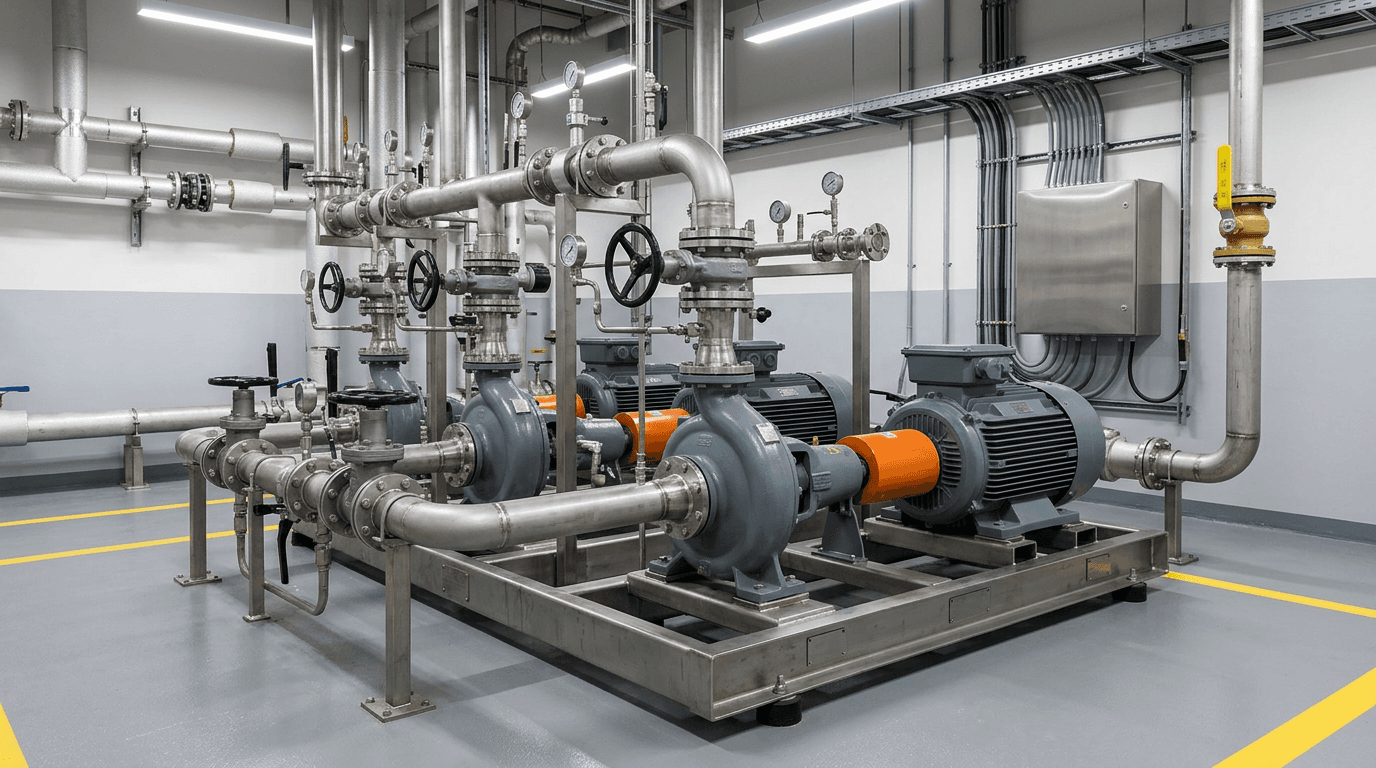
VFD-driven pump systems are used for flow control and energy management in process, water, HVAC, and OEM pump packages. PWM switching can couple common-mode voltage onto the motor shaft, and that shaft voltage may find a discharge path through bearings. Bearing damage can also come from lubrication, misalignment, contamination, or mechanical load. The useful next step is diagnosis—not an assumption that every failed pump bearing is an electrical event. A shaft grounding solution should be selected only after reviewing motor construction, shaft geometry, operating conditions, grounding, bearing arrangement, and installation constraints.
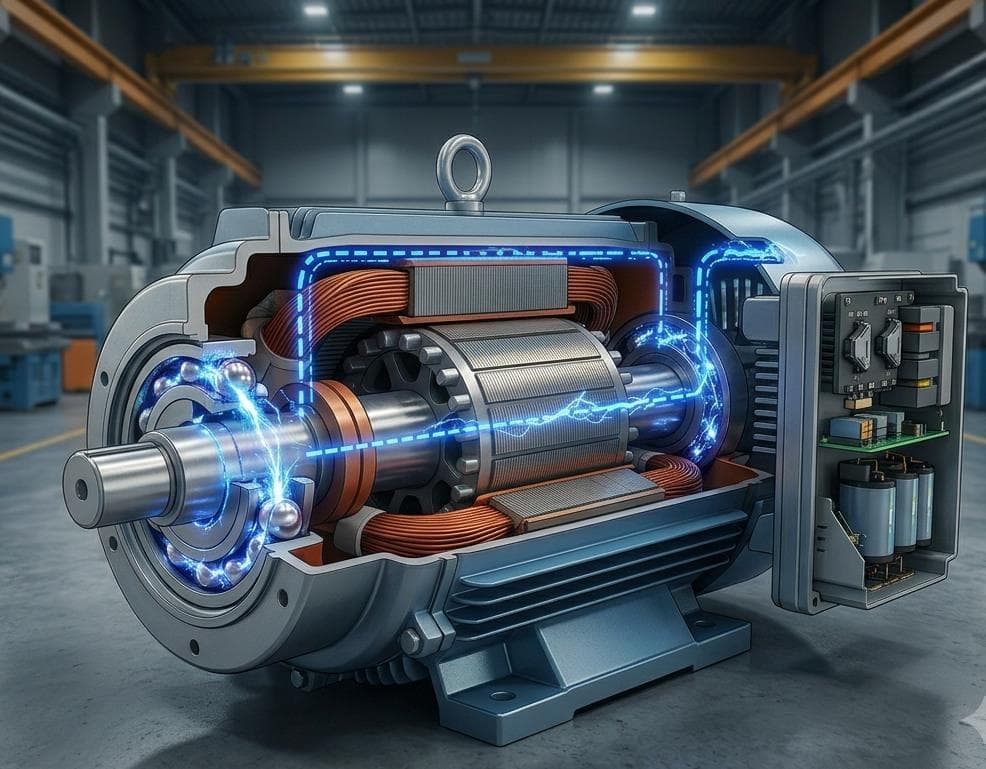
A variable-frequency drive switches rapidly. That PWM waveform can produce common-mode voltage at the motor. Capacitive coupling can then place voltage on the rotor and shaft. As shaft-to-frame voltage rises, it seeks a path. In some installations the bearing lubricant film is part of that path, and repeated discharge can contribute to electrical bearing damage. In other installations the film holds, another path dominates, or the observed failure is mechanical.
Shaft voltage is not bearing current. A high shaft-voltage reading does not prove that current is flowing through the bearing, and a bearing failure on a VFD pump motor is not automatically an electrical event. Mechanical, lubrication, and alignment issues can produce similar noise, vibration, and replacement cycles.
The items below are diagnostic clues. They help decide what to inspect next. Seeing one or more of them does not mean shaft current is the root cause.
A short replacement interval is a reason to inspect electrical and mechanical causes together. It does not, by itself, prove shaft current.
These patterns can be consistent with electrical discharge under rotation. Visual inspection still needs supporting operating context and, where possible, other evidence.
Noise can come from lubrication, contamination, mechanical load, or electrical wear. Treat it as a prompt to inspect, not as a diagnosis.
If vibration reappears after bearings are renewed, review alignment, lubrication, and whether an electrical discharge path may still be present.
A timing change after inverter conversion is a useful clue. Confirm drive settings, grounding, and mechanical condition before attributing the failure to shaft voltage.
Pump motors add packaging and duty constraints that change both measurement access and ring fit. These are review topics, not pass/fail scores.
Pump motors often run for long periods with limited inspection windows. Electrical and mechanical wear can accumulate before a scheduled stop.
Speed changes with process demand. Any later shaft-voltage comparison should use the same speed and load condition, not mixed operating points.
Coupling guards, close-coupled pumps, and enclosed NDE covers can limit where a ring can sit and which shaft end can be measured.
Washdown, moisture, and process contamination affect shaft surface condition, mounting durability, and how a contact path is reviewed.
Frame bonding, skid grounding, and driven-equipment earth paths change where current can travel. A ring on the motor does not automatically control every path.
Current can leave the motor through a coupling, pump, or connected piping if those parts offer a lower-impedance route than the intended ground path.
Existing motors may have little axial or radial envelope at the intended contact band. Structure and mounting method should follow the available space, not a catalog preference.
Use a staged engineering sequence. Skip steps only when the site cannot support them, and record what was not done.
Collect failure history, raceway appearance if available, noise or vibration notes, and whether symptoms followed a VFD retrofit. Separate electrical clues from lubrication and mechanical clues.
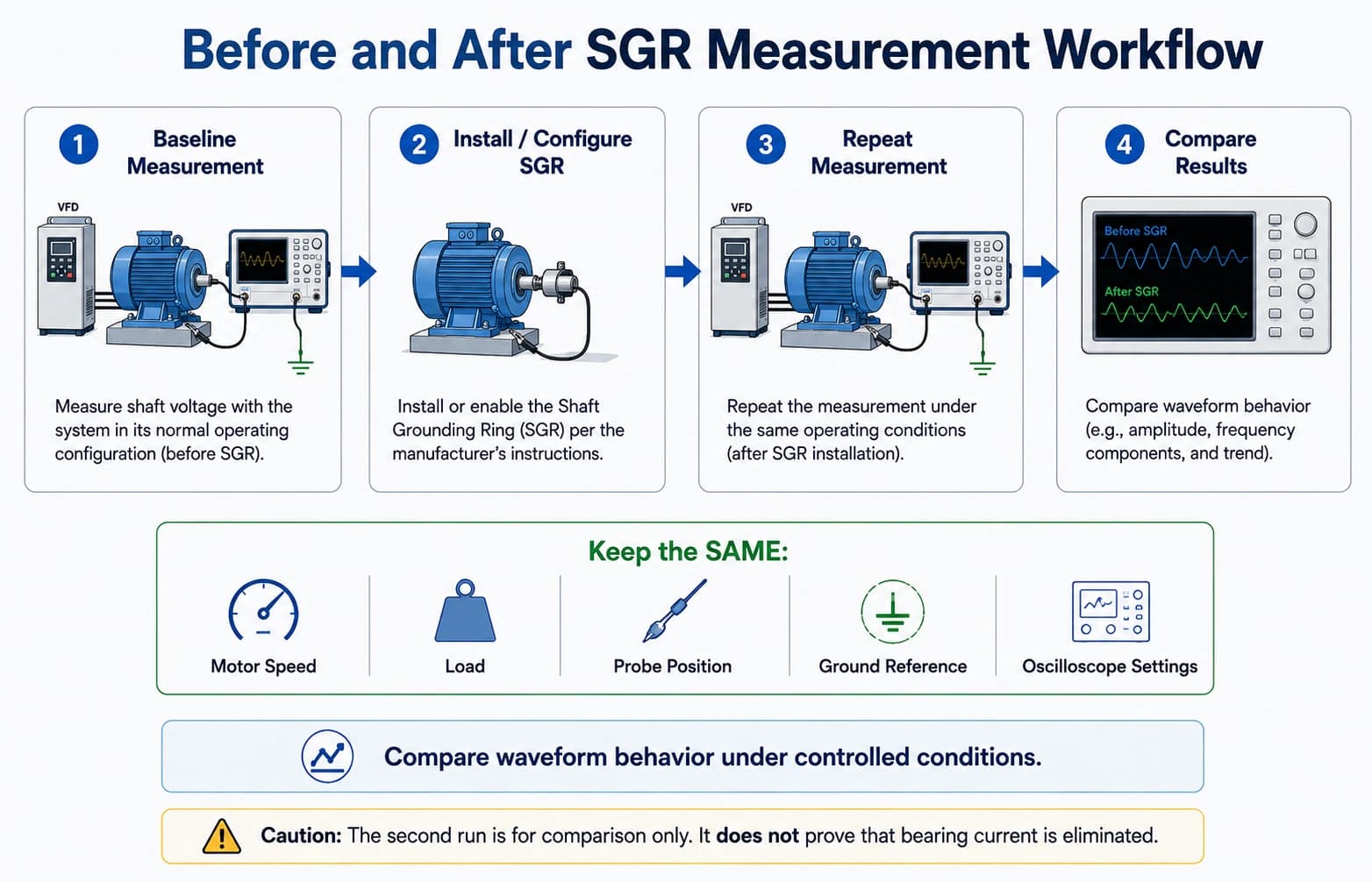
If an oscilloscope and safe shaft access are available, record shaft voltage with a documented probe position, frame reference, speed, load, and instrument settings.
Map bearings, insulated bearing if present, coupling, pump, frame bonding, and cable common-mode paths. Shaft voltage is not the same quantity as bearing current.
Choose a structure only after shaft diameter, access, envelope, mounting method, speed, and environment are known. Motor power alone is not a selection key.
Confirm a clean contact band, even fiber engagement, secure mounting, and a bonded path to the motor frame. A fitted ring that is not grounded is not a completed path.
Repeat the shaft-voltage check under the same speed, load, probe, reference, and instrument settings. Use the pair as one review input, not as a universal pass/fail test.
RD/RDW, ST/STW, and custom rings use the same grounding purpose: a conductive-fiber path that can divert shaft current away from bearings when correctly fitted. The practical difference is structure, mounting method, and fit to the shaft and envelope.
Do not select a series from motor power alone. Review shaft diameter at the contact band, accessible installation position, axial and radial envelope, mounting method, operating speed, environment, drawing or photo, and bearing arrangement.
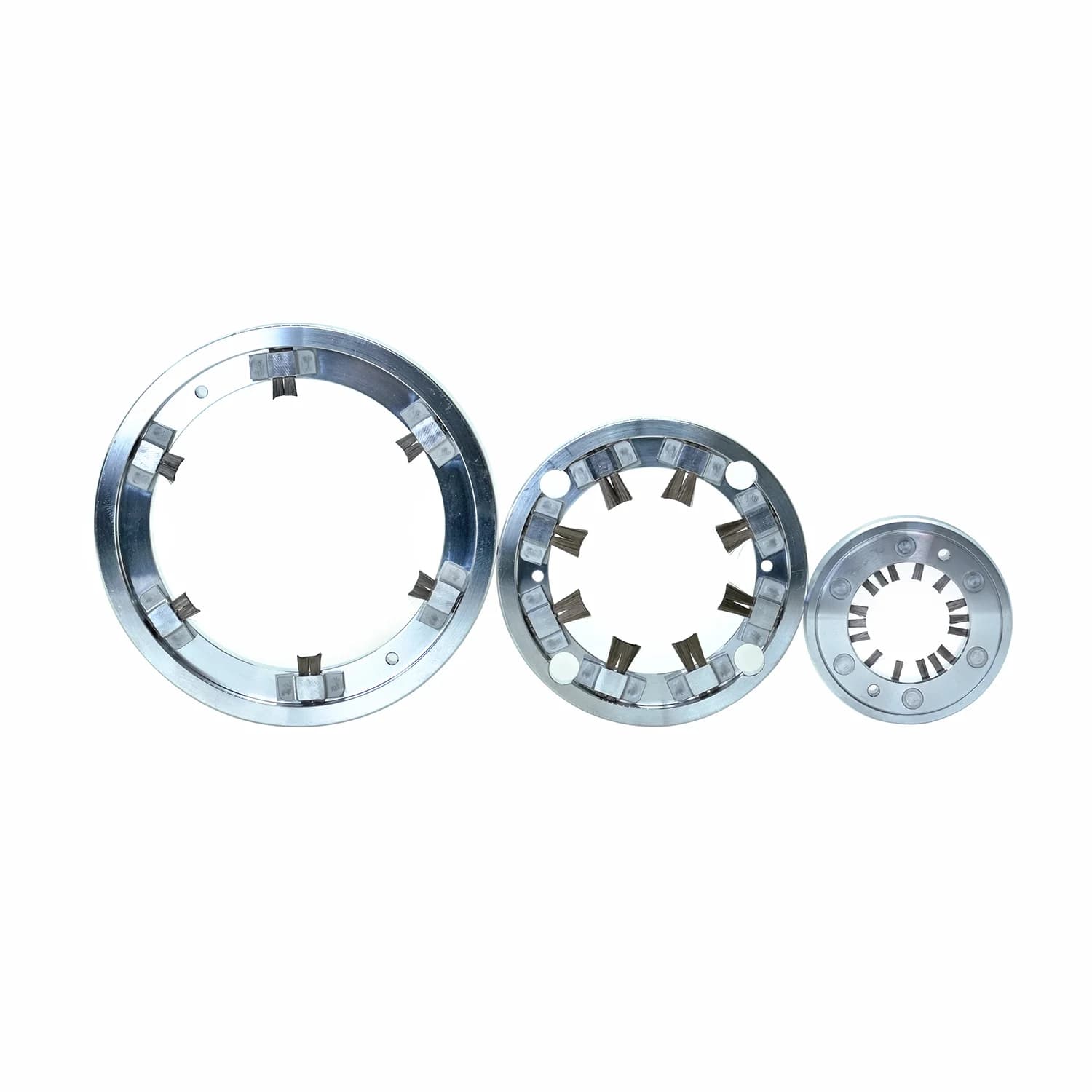
Review the solid RD/RDW family where shaft diameter, mounting envelope, and assembly conditions support a solid ring. Interference-fit or screw-fastened mounting is confirmed by application, not assumed from catalog.
View product familyReview the arc-shaped ST/STW family where shaft diameter, access, or envelope is better suited to an arc-shaped structure. Screw-fastened mounting is typically reviewed against the available space.
View product familyUse a drawing-led custom review when RD/RDW or ST/STW cannot match shaft geometry, contact position, or installation envelope. Side or end contact can be reviewed from photos and drawings.
View product familySend the items you have. Incomplete packages still start a conversation; they only limit how specific the first comment can be.
If an oscilloscope is available, capture a baseline and a post-installation waveform under the same speed, load, probe position, grounding reference, and instrument settings. A lower displayed shaft voltage under that specific condition suggests a lower-impedance shaft-to-frame path is present. It does not prove that every bearing-current path is controlled, and it is not a universal voltage pass/fail threshold.
How to Measure Shaft Voltage in VFD Motors
No. A shaft grounding ring is intended to provide a controlled shaft-to-frame discharge path. Bearings can still fail from lubrication, contamination, misalignment, mechanical load, or other electrical paths that the ring does not control.
Send shaft diameter, motor drawing or photo, rated and maximum speed, VFD information, bearing arrangement, and available mounting space. Add a waveform screenshot if you have one.
Use the form below or the review button. Include the checklist items so the first engineering reply can address fit, not only catalog diameter.
