Shaft Grounding Ring vs. Carbon Brush: An Engineering Comparison for VFD Motors
|
Engineering comparison of conductive-fiber shaft grounding rings and carbon brush grounding for VFD motors, covering shaft current formation, contact mechanisms, application fit, and the operating data needed for selection.
VFD-driven motors can develop shaft voltage and bearing current that lead to electrical discharge damage. Two common shaft grounding approaches are carbon brush assemblies and conductive-fiber shaft grounding rings. They share the same objective—provide a controlled path for shaft current—but differ in contact geometry, maintenance expectations, and integration constraints.
This article compares the two methods from an engineering perspective. It is not a universal ranking. The appropriate choice depends on motor speed, duty cycle, installation access, environmental conditions, and how the motor is grounded.
How Shaft Current Forms in VFD Motor Systems
A variable frequency drive converts fixed-frequency AC power into a PWM output to control motor speed. High-speed switching in the inverter creates common-mode voltage on the motor windings and frame. Capacitive coupling between the rotor and stator can charge the shaft relative to ground.
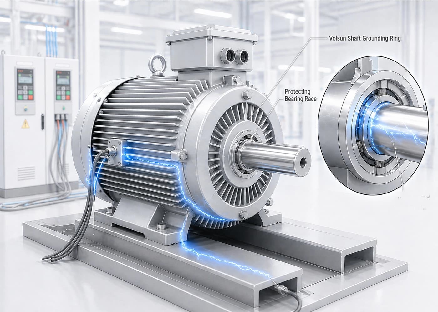
When shaft voltage rises, the bearing lubricant film may break down. Current can then discharge through the rolling elements and raceways, causing pitting, frosting, or fluting over time. Without a defined low-impedance discharge path, the bearings may become the default path for high-frequency shaft current.
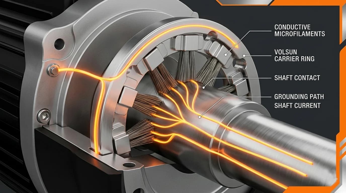
Shaft grounding is one way to redirect current away from the bearing interface. Whether a carbon brush or a conductive-fiber ring is more suitable depends on how reliably each can maintain contact under the actual speed, environment, and mechanical constraints of the application.
How a Carbon Brush Grounding System Works
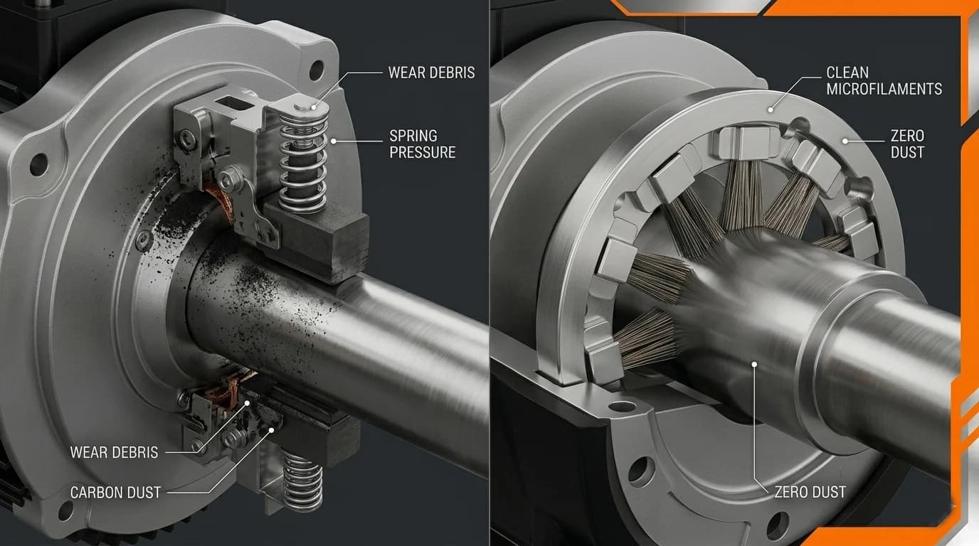
A traditional carbon brush grounding assembly uses a spring-loaded graphite block pressed against the rotating shaft. The brush slides on the shaft surface and transfers current to a holder connected to the motor frame or an external ground point.
- Single-point contact on the shaft circumference
- Spring force maintains brush pressure as the brush wears
- Graphite-to-shaft interface carries the discharge current
- Holder and grounding wire complete the path to frame ground
Carbon brushes are widely understood and can be retrofitted on many motor platforms. In inverter-duty service, engineers should evaluate brush wear rate, debris generation, contact stability at speed, and the inspection interval required to maintain a reliable ground path.
How a Conductive-Fiber Shaft Grounding Ring Works
A conductive-fiber shaft grounding ring mounts around the shaft so that metallized carbon fibers or similar conductive elements lightly contact the shaft surface. Multiple fibers around the circumference share contact duty instead of relying on one brush point.
- Circumferential fiber contact along the shaft
- Current transfers from shaft through fibers to the ring body
- Ring body or bracket connects to the grounded motor frame
- Solid, split, or custom ring forms adapt to installation access
The design intent is to provide a continuous low-impedance path for high-frequency shaft current while spreading mechanical contact over many small fiber tips. Performance still depends on correct installation, shaft surface condition, fiber pressure, and grounding integrity.
Engineering Comparison: Carbon Brush vs. Conductive-Fiber Ring
The table below summarizes typical engineering trade-offs. Actual results vary with motor platform, speed, environment, and maintenance practice.
- Contact geometry: single brush point vs. distributed fiber contact around the shaft
- Maintenance: brushes typically require periodic inspection and replacement; rings may reduce brush replacement cycles but still need installation and continuity checks
- Debris and cleanliness: brush wear can generate carbon dust; fiber contact may produce less brush-style particulate but still requires a clean shaft surface
- Shaft surface effect: concentrated brush contact can groove or polish local areas; distributed fiber contact can spread mechanical load but does not eliminate shaft interaction
- High-speed behavior: brush bounce or film breakdown can interrupt contact; ring performance depends on fiber compliance, runout, and surface condition at operating speed
- Integration: brush holders suit some retrofit envelopes; rings require radial space and a secure mount aligned to the contact zone
Where Each Approach May Fit
Carbon brush grounding may be considered when
- Existing brush hardware and maintenance routines are already established on the platform
- Installation space favors a compact holder on one side of the shaft
- Operating speed and duty cycle stay within the brush and holder rating
- Inspection and replacement intervals are acceptable in the maintenance plan
Conductive-fiber shaft grounding rings may be considered when
- Continuous-duty or higher-speed VFD applications need a circumferential contact path
- Reducing brush replacement cycles and carbon dust near seals or lubricants is a priority
- The motor envelope can accommodate a ring mount with stable fiber-to-shaft contact
- A defined grounding path to frame is available and can be verified after installation
Some projects use insulated bearings or hybrid strategies to manage circulating currents. Shaft grounding addresses shaft-to-frame discharge but does not replace a full review of drive topology, cable routing, and system grounding.
Eight Parameters to Submit for Selection Review
To compare carbon brush and conductive-fiber ring options for a specific motor, provide the following operating and mechanical inputs:
- Motor type and application (pump, fan, compressor, traction, etc.)
- Drive type and inverter topology, if known
- Shaft diameter and tolerance at the intended contact location
- Rated speed and maximum operating speed
- Available radial and axial space for a brush holder or ring mount
- Operating environment, including temperature, humidity, oil exposure, and dust or contamination
- Bearing insulation arrangement and motor grounding configuration
- Motor drawing, photos, or measured shaft voltage / shaft current data if available
These inputs support a preliminary review of contact feasibility, mounting options, and whether brush maintenance or ring integration better matches the duty profile. Final configuration should be validated under application-relevant conditions.
Installation Affects Grounding Performance
Both methods depend on installation quality. The shaft contact zone should be clean, the ground connection verified, and continuity checked after assembly. For conductive-fiber rings, fiber contact should be even and the mount secured against vibration.
Summary
Carbon brushes and conductive-fiber shaft grounding rings both aim to divert shaft current away from motor bearings in VFD applications. Brushes rely on a maintained single-point contact; rings use distributed fiber contact around the shaft. Neither removes the need for correct grounding, environmental control, or application-specific validation.
For a project-specific comparison, share motor operating conditions and installation constraints so the grounding approach can be reviewed against the actual duty profile.
Submit Motor Operating Conditions
Related technical resources: Why VFD Motors Need Shaft Grounding Rings to Prevent Bearing Failure
Need sizing help?
Send motor nameplate data and shaft diameter - we respond within 24 hours.
Submit Motor Operating Conditions