What Causes Shaft Voltage in VFD Motors?
|
VFD-driven motors can develop shaft voltage through PWM switching, common-mode voltage, high dv/dt, and parasitic capacitance. Understand the electrical mechanism from DC bus to bearing discharge.
A variable frequency drive does not output a perfect sine wave. It synthesizes motor voltage through fast semiconductor switching, and that switching is the origin of shaft voltage in VFD motors. The path runs from the DC bus, through pulse-width modulation, to a common-mode voltage on the motor, then through parasitic capacitance to a rotor and shaft potential, and finally to a discharge across the bearing lubricant film. This article explains each step of that mechanism. It is not a buying guide; for protection options, follow the solution links at the end.
1. PWM Switching Creates Common-Mode Voltage
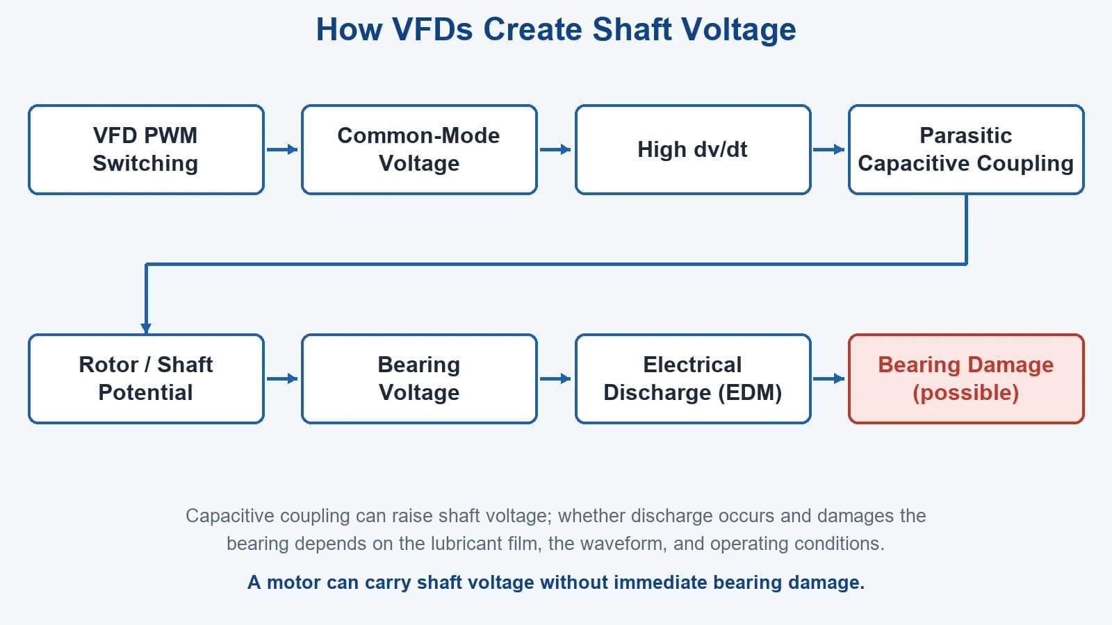
A VFD first rectifies incoming AC to a DC bus, then uses insulated-gate switches, typically IGBTs, to chop that DC into a PWM waveform that approximates the desired motor voltage. The three phase legs do not switch symmetrically at every instant, so the average of the three terminal voltages relative to the DC midpoint, the common-mode voltage, carries high-frequency content. The motor windings and frame sit on top of this common-mode potential.
The practical consequence for a motor or maintenance engineer is not the switching math but the result: fast voltage edges appear between the windings, the frame, and everything capacitively tied to them. Those edges are what later couple onto the shaft.
2. High dv/dt Increases Capacitive Coupling
Each switching transition is a voltage step divided by a very short time, expressed as dv/dt. Because capacitive current through any capacitance C is approximately C multiplied by dv/dt, a steeper edge drives larger instantaneous capacitive current through every parasitic capacitance in the motor system.
This raises the electrical conditions that can drive high-frequency shaft and bearing currents. It does not by itself guarantee bearing damage, because whether discharge becomes harmful depends on the bearing film, the actual waveform, and the motor construction. The mechanism is permissive, not deterministic.
3. Parasitic Capacitance Couples Voltage to the Rotor
Inside a motor, capacitance is not something installed; it is the geometry of the machine. The stator winding sits close to the rotor across a thin air gap and insulation, forming a stator-to-rotor capacitance, often written Csr. The rotor sits close to the grounded frame, forming a rotor-to-frame capacitance, Crf. The bearing, with its thin lubricant film, forms a small bearing capacitance, Cb. Together these act as a capacitive divider across the common-mode voltage.
Because the rotor is coupled to the frame through Crf and to the shaft through its own conductor, the common-mode voltage divides among these paths. The key step is that the rotor, and therefore the shaft, rises to a potential relative to the grounded frame. The shaft is not isolated; it is charged through distributed capacitance that exists whether or not anyone drew it on a schematic.
- Stator winding to rotor (Csr)
- Rotor to frame (Crf)
- Bearing lubricant film (Cb)
4. How Rotor Voltage Becomes Shaft Voltage
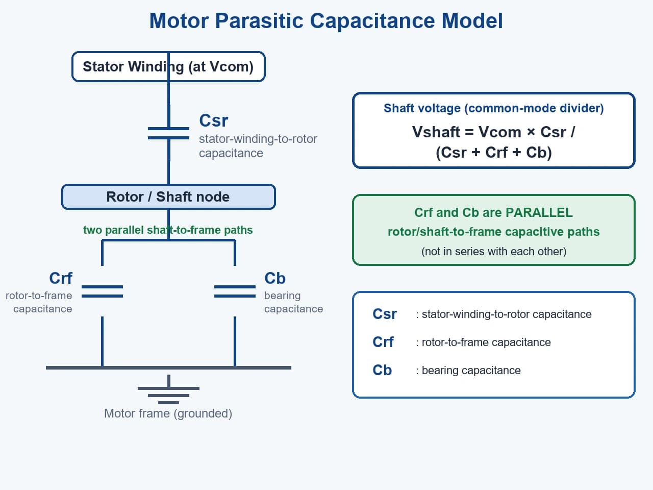
Shaft voltage is the electrical potential difference between the rotating shaft and the grounded motor frame. Because the rotor and shaft are the same conductor, the rotor potential appears on the shaft. The stator-to-rotor capacitance Csr couples the winding to the rotor/shaft node, while the rotor-to-frame capacitance Crf and the bearing capacitance Cb are parallel paths from that node to the motor frame; both are part of the network that sets how much of the common-mode voltage reaches the shaft.
The distinction that matters for diagnosis is that shaft voltage is not bearing current. Shaft voltage is a standing potential; bearing current is what flows when that potential finds a discharge path. A motor can show shaft voltage without yet sustaining bearing current, and the two are measured and interpreted differently.
For the definition and the difference from bearing current: What Is Shaft Voltage?
5. When Shaft Voltage Becomes Bearing Current
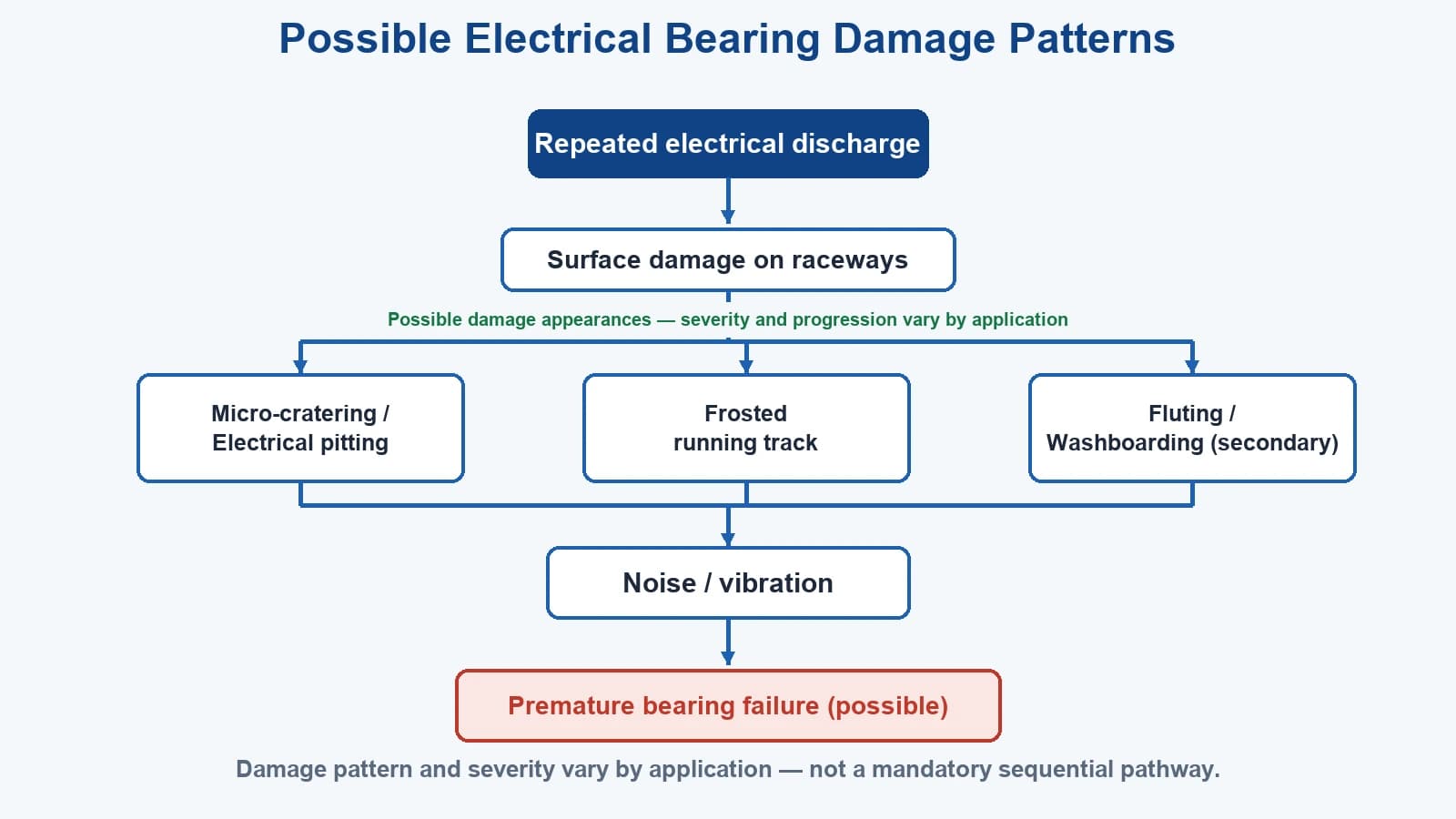
In normal operation the rolling elements are separated from the raceways by a thin lubricant film that behaves electrically like an insulator until it does not. As the shaft-to-frame voltage rises, the film across the bearing can exceed its withstand at a point, and a micro-discharge passes through the contact. Repeated discharges across the raceway are the mechanism behind pitting and fluting.
There is no single voltage value above which every bearing will fail. The withstand of the film depends on film thickness, speed, temperature, load, lubricant condition, and the waveform shape, not on a fixed threshold. Claiming a universal rule such as install a grounding ring above X volts would be technically unsound; the correct approach evaluates the motor, the drive, and the measured waveform together.
6. EDM Bearing Current vs Circulating Bearing Current
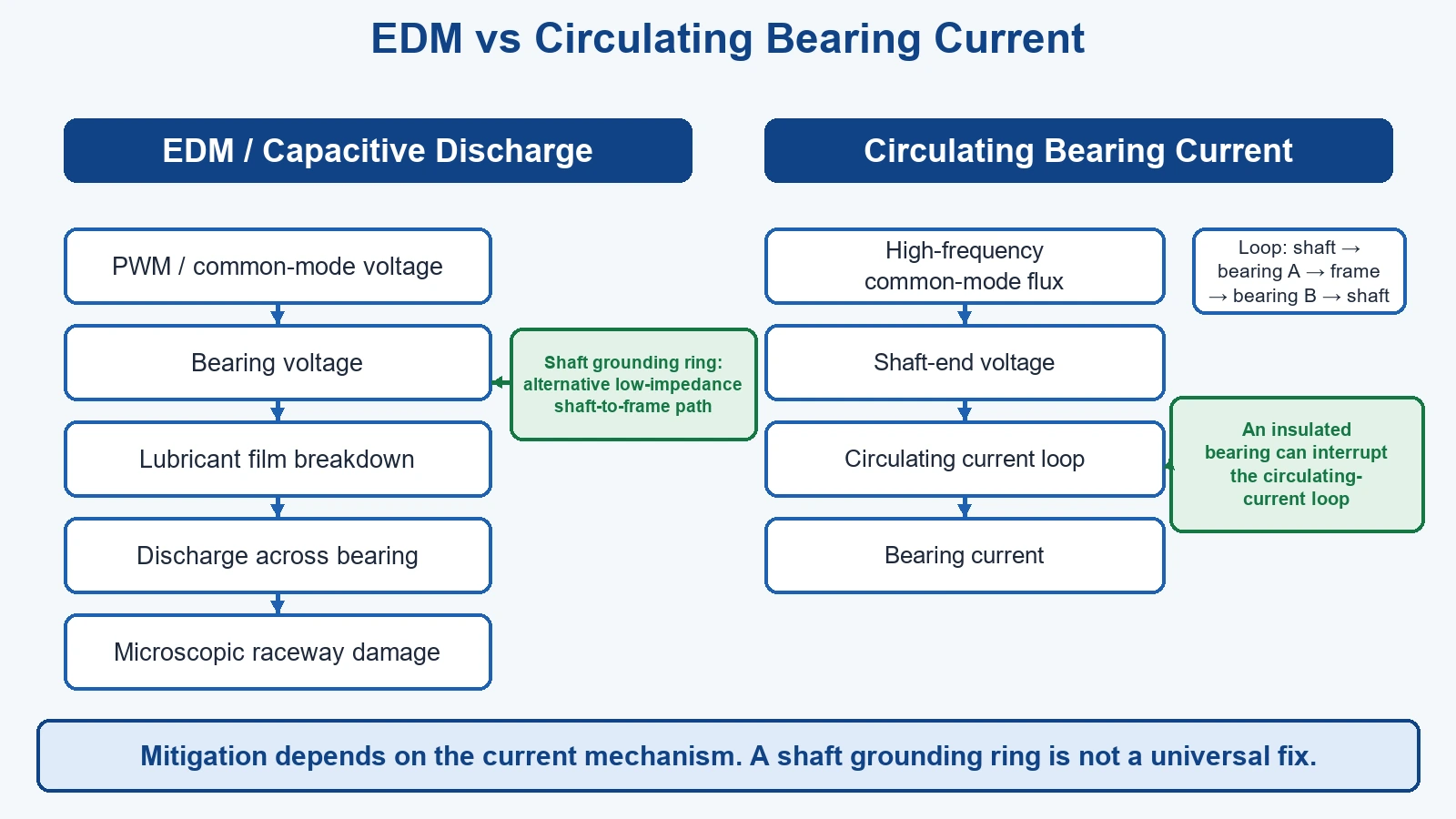
Bearing current is not one phenomenon. Two paths are commonly distinguished:
- Capacitive, or EDM, discharge current: the shaft-to-frame discharge described above, where shaft voltage breaks down the bearing film and current jumps the raceway.
- Circulating bearing current: a loop current through the shaft, one bearing, the frame, the other bearing, and back, driven by asymmetry in the magnetic or capacitive circuit rather than only by the shaft-to-frame potential.
These have different dominant causes and different preferred mitigations. A grounding ring addresses the shaft-to-frame discharge path; an insulated bearing on one end addresses the circulating loop. Correct mitigation depends on identifying the dominant current path before selecting hardware.
7. What Makes Shaft Voltage Problems More Likely?
Risk is elevated, not guaranteed, by several factors:
- Fast switching edges and high carrier or switching frequency
- Long motor cable runs, which can increase reflected-wave and common-mode effects
- Motor frame grounding and bonding quality
- Motor size and frame configuration, because larger machines can present different capacitive and loop paths
- Bearing arrangement and whether insulated bearings are already present
- Coupling and driven equipment that may provide secondary discharge paths
- Drive topology and the overall system grounding architecture
None of these alone determines the outcome. They raise the probability that shaft voltage reaches a level and path where bearing discharge becomes a reliability concern.
8. How to Confirm Whether Shaft Voltage Is the Problem
Shaft voltage is confirmed by measurement, not assumption. Probe placement, oscilloscope setup, waveform review, and before-and-after comparison are covered in the dedicated measurement guide. This article does not repeat that procedure; the point is to confirm the mechanism before acting on it.
For the field procedure: How to Measure Shaft Voltage in VFD Motors
9. How Shaft Voltage Is Mitigated
Once shaft voltage and its discharge path are understood, mitigation is a system decision:
- Shaft grounding: provide a controlled low-impedance path from shaft to grounded frame so discharge does not traverse the bearing, typically with a shaft grounding ring.
- Insulated bearing: raise the impedance of a specific bearing path, often used for circulating-current control.
- Grounding and bonding improvement: reduce common-mode exposure through better frame bonding and cable practice.
- Common-mode mitigation at the drive: filters, reactors, or cable measures that reduce the voltage stress reaching the motor.
The choice depends on the dominant current path. For the justification of why a grounding ring is used, see the dedicated article; for a direct comparison with insulated bearings, see the comparison guide.
Why a controlled path is used: Why VFD Motors Need Shaft Grounding Rings
Ring or insulated bearing: Shaft Grounding Ring vs. Insulated Bearing
When a ring is the chosen path: how to install a shaft grounding ring
Frequently Asked Questions
What causes shaft voltage in VFD motors? VFD switching creates a high-frequency common-mode voltage; parasitic capacitance inside the motor couples part of that voltage onto the rotor and shaft, producing a shaft-to-frame potential that can discharge through the bearings.
Is shaft voltage the same as bearing current? No. Shaft voltage is a potential difference between the shaft and the grounded frame; bearing current is the current that flows when that potential discharges, usually across the bearing lubricant film.
What is common-mode voltage in a VFD motor? It is the high-frequency voltage that appears between the motor phase terminals on average and the DC bus midpoint, produced by the drive PWM switching. The motor structure sits on top of it.
How can shaft voltage be measured? With a high-bandwidth probe referenced to the motor frame and an oscilloscope set to capture the PWM-related waveform; see the measurement guide for probe placement and before-and-after comparison.
Does every VFD motor need a shaft grounding ring? No. Whether protection is needed depends on the current mechanism, bearing arrangement, grounding, the measured waveform, and the motor and VFD system architecture, not on motor power, shaft diameter, or a fixed voltage threshold alone.
Need sizing help?
Send motor nameplate data and shaft diameter - we respond within 24 hours.
Contact & RFQ