How to Select a Shaft Grounding Ring for EC and VFD Motors
|
A practical engineering guide to selecting shaft grounding rings for EC and VFD motors, covering shaft dimensions, speed, fiber configuration, installation, environment and validation.
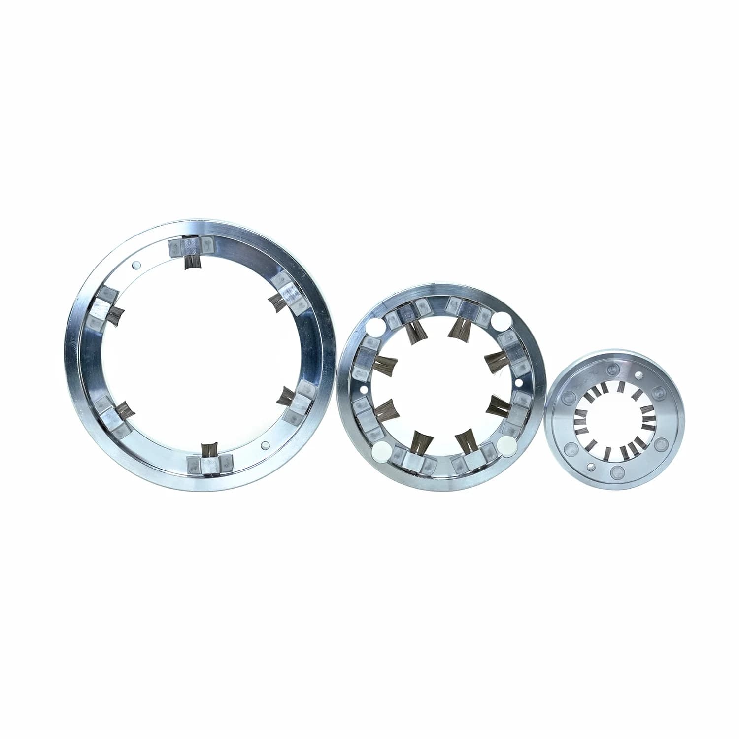
Selecting a shaft grounding ring is not only a catalog matching exercise. The goal is to help create a stable, low-impedance path that can divert shaft current away from the motor bearings under real operating conditions. Motor power rating alone is not enough.
For background on why inverter-fed motors can develop shaft voltage and bearing current risk, see our guides on why VFD motors need shaft grounding rings and what causes VFD bearing failure. This article focuses on the inputs needed to select and evaluate a solution for EC motors and VFD-driven industrial motors.
A Four-Step Selection Process
- Confirm electrical and grounding architecture — understand where shaft current can flow and how the motor is grounded.
- Define the mechanical contact interface — shaft diameter, tolerance, surface condition, contact position, and runout if available.
- Select ring structure and mounting method — solid, arc-shaped, or custom/integrated forms may be considered based on access and packaging.
- Validate operating and life requirements — speed profile, environment, inspection expectations, and application-relevant confirmation.
These steps keep electrical, mechanical, packaging, and service questions in order before product comparison begins.
Quick Selection Summary
Collect these application inputs before reviewing product options:
- Shaft diameter and tolerance — ring size, fit, and contact geometry
- Shaft surface condition — contact quality of conductive fibers
- Rated and maximum speed — contact stability under duty extremes
- Duty cycle — continuous, intermittent, and cycling wear stress
- Shaft voltage — electrical stress indicator, not a complete sizing input
- Shaft current, if available — supports review when measurement quality is reliable
- Grounding architecture — possible current paths in the system
- Installation space — structure type and mounting options
- Environment — temperature, humidity, oil, dust, and contamination
- Required service life — separate motor life from device wear and inspection intervals
- Drawing or 3D model — realistic fit and clearance review
Structure Direction Table
The following are possible directions only. Final choice depends on shaft size, access, envelope, and mounting review.
- Solid ring (RD/RDW) — May be considered when the shaft and housing envelope support a continuous ring with confirmed OEM fit.
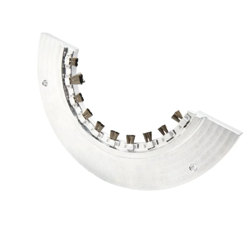
- Arc-shaped ring (ST/STW) — May be considered for larger shaft diameters or access-constrained motors where an arc housing can simplify mounting.
- Integrated / custom structure — May be considered for non-catalog geometry, special end-shield integration, or constrained envelopes.
Compare RD/RDW and ST/STW families: ST/STW vs RD/RDW: Which Shaft Grounding Ring Structure?
Solid shaft grounding ring (RD/RDW)
Arc-shaped shaft grounding ring (ST/STW)
EC Motors vs VFD-Driven Industrial Motors
Both EC motors and industrial motors with external VFDs can face bearing current risk, but installation and evaluation constraints often differ.
EC motors are frequently compact and highly integrated. Installation space may be limited, and the contact zone may depend on enclosure design, bearing insulation strategy, and casing access. Retrofit can be difficult without housing review.
VFD-driven industrial motors are more often treated as separate drive-motor systems. There may be more room for solid or arc-shaped rings, but grounding can still be complex due to couplings, driven equipment, and existing grounding devices.
In both cases, ask the same question: can the device maintain stable conductive-fiber contact and a controlled discharge path under the motor’s speed, envelope, environment, and grounding layout?
Shaft Diameter, Tolerance and Surface Condition
Shaft diameter is usually the first dimensional input, but it is rarely enough. Provide nominal diameter, manufacturing tolerance if available, and the intended contact position.
Tolerance matters because conductive-fiber engagement depends on the actual shaft diameter at the contact zone, not only a nameplate value. If tolerance data is unavailable, drawings and measured diameters become more important.
Surface condition is equally important:
- Shaft material influences conductivity and wear at the contact interface.
- Coating or oxidation can raise contact resistance or reduce fiber effectiveness.
- Contamination from dust, oil film, coolant, or process debris can interrupt contact.
- Contact position should avoid keyways, steps, grooves, sharp edges, or damaged zones whenever possible.
- Shaft runout and concentricity, when available, help estimate contact continuity under rotation.
A ring sized only by nominal diameter may still underperform if the contact surface is oxidized, contaminated, or poorly positioned.
Rated Speed, Maximum Speed and Duty Cycle
Review speed as a set of operating conditions. Share both rated speed and maximum speed that can occur in service.
- Continuous or intermittent operation
- Short-duration maximum-speed operation, rapid acceleration or deceleration, and intermittent high-speed duty
- Typical operating hours, if known
These inputs do not create a universal safe-speed chart. They help evaluate whether contact stability, friction and wear fit the installation envelope and planned inspection practice.
Shaft Voltage, Shaft Current and Grounding Architecture
Shaft voltage indicates electrical stress. Shaft current data, when measured reliably, can further support review. Electrical values must still be interpreted with grounding architecture.
- Motor frame grounding practice
- Insulated bearing arrangement
- Drive-end versus non-drive-end constraints
- Coupling style and driven-equipment grounding path
- Existing grounding devices or filters
- Expected common-mode current path through the motor and connected machinery
Shaft-voltage and shaft-current results should be reviewed together with the measurement method, probe position, grounding reference and instrument bandwidth. Where possible, provide a measurement setup description or waveform screenshot.
For the test setup and waveform review procedure: How to Measure Shaft Voltage in VFD Motors
A shaft grounding ring is only one element in bearing current protection. An insulated bearing may change where current tries to flow. A weakly bonded frame or an alternate path through coupled equipment can move risk rather than remove it.
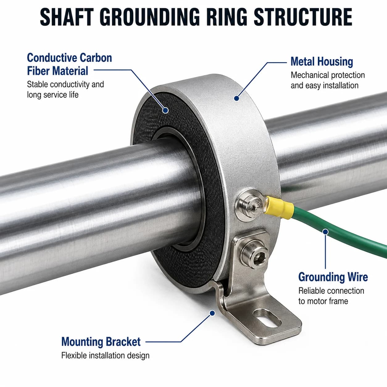
Why Shaft Voltage Alone Cannot Determine the Number of Conductive Fiber Bundles
Shaft voltage alone cannot determine the required number and arrangement of conductive fiber bundles.
Voltage amplitude is useful, but it does not fully describe contact geometry, waveform quality, surface films, speed stability, clearance limits, duty cycle, or whether another grounding method already alters the current path.
Two motors with similar measured shaft voltage can still need different designs if shaft finish, speed profile, housing space, and grounding architecture differ.
How Many Conductive Fiber Bundles Are Needed?
More conductive fiber bundles do not automatically mean better grounding performance.
The number and arrangement of conductive fiber bundles is a trade-off among contact opportunities, stability under speed and runout, friction and wear, installation limits, and service assumptions.
Increasing bundle count may improve contact redundancy in some layouts. In others, it may increase friction or wear in some configurations, complicate packaging, or add little benefit if surface condition, mounting quality, or grounding paths are the real bottlenecks.
Define contact and discharge needs first, then evaluate a metallized carbon fiber configuration that balances conductivity, contact stability, friction and wear, installation space, and serviceability.
Installation Space and Mounting Method
Installation constraints often decide which structure direction is realistic. Check radial and axial clearance, assembly access, housing geometry, fasteners, and whether partial disassembly is possible.
OEM designs usually allow earlier packaging decisions. Retrofit work may favor arc-shaped or custom approaches. Confirm that mounting can place conductive fibers on a suitable shaft zone and bond to the intended ground path.
For installation process detail, see: How to Install a Shaft Grounding Ring
Distorted housings, uneven fastening, or contact against damaged shaft surfaces can reduce field performance, even when the electrical concept looks correct on paper.
Temperature, Humidity, Lubrication and Contamination
Operating environment affects contact quality and wear expectations. Provide temperature, humidity, oil or coolant exposure, dust or process contamination, and chemical exposure if relevant.
Lubrication can help mechanical systems and still challenge electrical contact if a dielectric film builds between conductive fibers and the shaft. Dust can abrade or interrupt contact. Describe the actual environment rather than calling it normal industrial conditions.
Service Life, Inspection and Validation
Keep service-life language precise. Do not mix these concepts:
- Motor design life — intended life target of the motor platform
- Wear life of conductive fibers — contact-element wear under the actual duty
- Inspection interval — when contact, continuity, and contamination should be reviewed
- Replacement interval — when replacement is planned or triggered by inspection
- Motor-level validation — confirmation under application-relevant motor conditions
Motor design life and grounding-device maintenance expectations must be evaluated separately. Where life targets are critical, define success criteria clearly. Final configuration requires application-specific validation.
Technical Evaluation Checklist
Minimum Information for Preliminary Review
- Motor type and application
- Drive type
- Rated and maximum speed
- Shaft diameter and tolerance
- Available radial and axial installation space
- Basic operating environment, including temperature and any oil, dust or contamination
- 2D drawing, photos, or basic envelope sketch
Helpful Information for Detailed Engineering Evaluation
- Operating duty cycle
- Shaft material and surface condition
- Shaft runout, if available
- Measured shaft voltage
- Measured shaft current or waveform, if available
- Measurement method, probe position, grounding reference, and instrument bandwidth
- Bearing insulation arrangement
- Motor grounding configuration and known common-mode path comments
- Operating temperature and humidity
- Lubrication, oil, dust, or contamination conditions
- Expected motor design life and inspection requirements
- 3D model or detailed installation drawing
Project Information
Annual demand or project volume and timeline or sample quantity, if relevant. Annual demand supports commercial planning. It is not a technical sizing parameter.
Selecting the Right Shaft Grounding Solution
A properly selected and installed shaft grounding ring can help establish a stable, low-impedance discharge path from the shaft to the grounded motor frame. Its effectiveness depends on the motor’s mechanical interface, electrical architecture, operating environment and validation conditions.
The objective is not to choose the largest ring or the greatest number of conductive fiber bundles. It is to identify the configuration that provides stable electrical contact, suitable mechanical integration and practical service life for the specific motor application.
Need help selecting a shaft grounding solution?
Send us your shaft dimensions, motor speed, installation drawing and operating conditions for a preliminary engineering review.
Request an Engineering Evaluation
Related technical resources: Why VFD Motors Need Shaft Grounding Rings to Prevent Bearing Failure
What Causes VFD Bearing Failure?
Need sizing help?
Send motor nameplate data and shaft diameter - we respond within 24 hours.
Contact & RFQ