What Causes VFD Bearing Failure? Electrical Erosion, Fluting, and Diagnosis
|
Repeated bearing replacement, abnormal noise, vibration, and fluting on VFD motors may point to electrical erosion—but lubrication and mechanical damage can look similar. Learn how to diagnose carefully, approach shaft-voltage checks, and decide when shaft grounding may help.
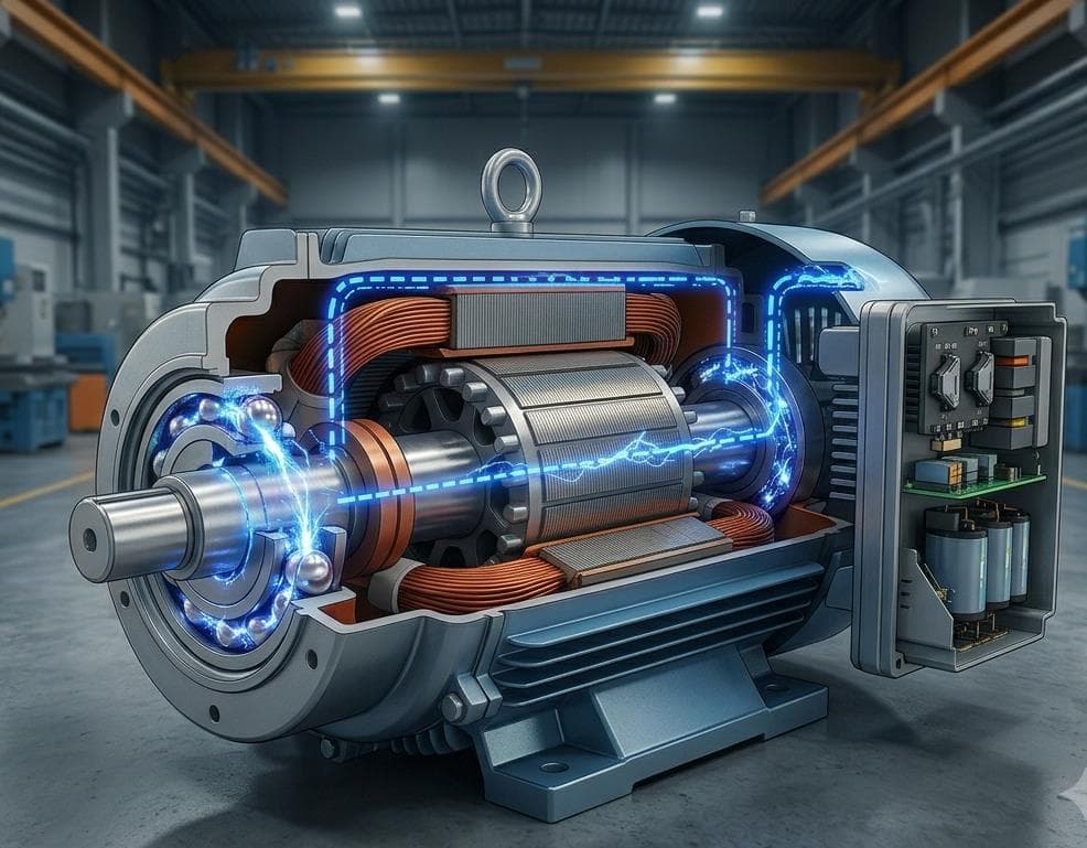
In many plants, the first sign of trouble is not a laboratory measurement. It is a motor that keeps returning for bearing replacement, unusual noise after only a few months of service, rising vibration, or a raceway that shows washboard-like fluting when the bearing is opened.
Variable frequency drives (VFDs) improve speed control and energy efficiency. They may also contribute to shaft voltage and bearing current in inverter-fed motors. When that current repeatedly discharges across the lubricant film, electrical erosion can shorten bearing life. Mechanical issues—lubrication, contamination, misalignment, preload, installation error, and mechanical load—can produce similar symptoms, so careful diagnosis is required before selecting protection.
How Shaft Voltage May Damage VFD Motor Bearings
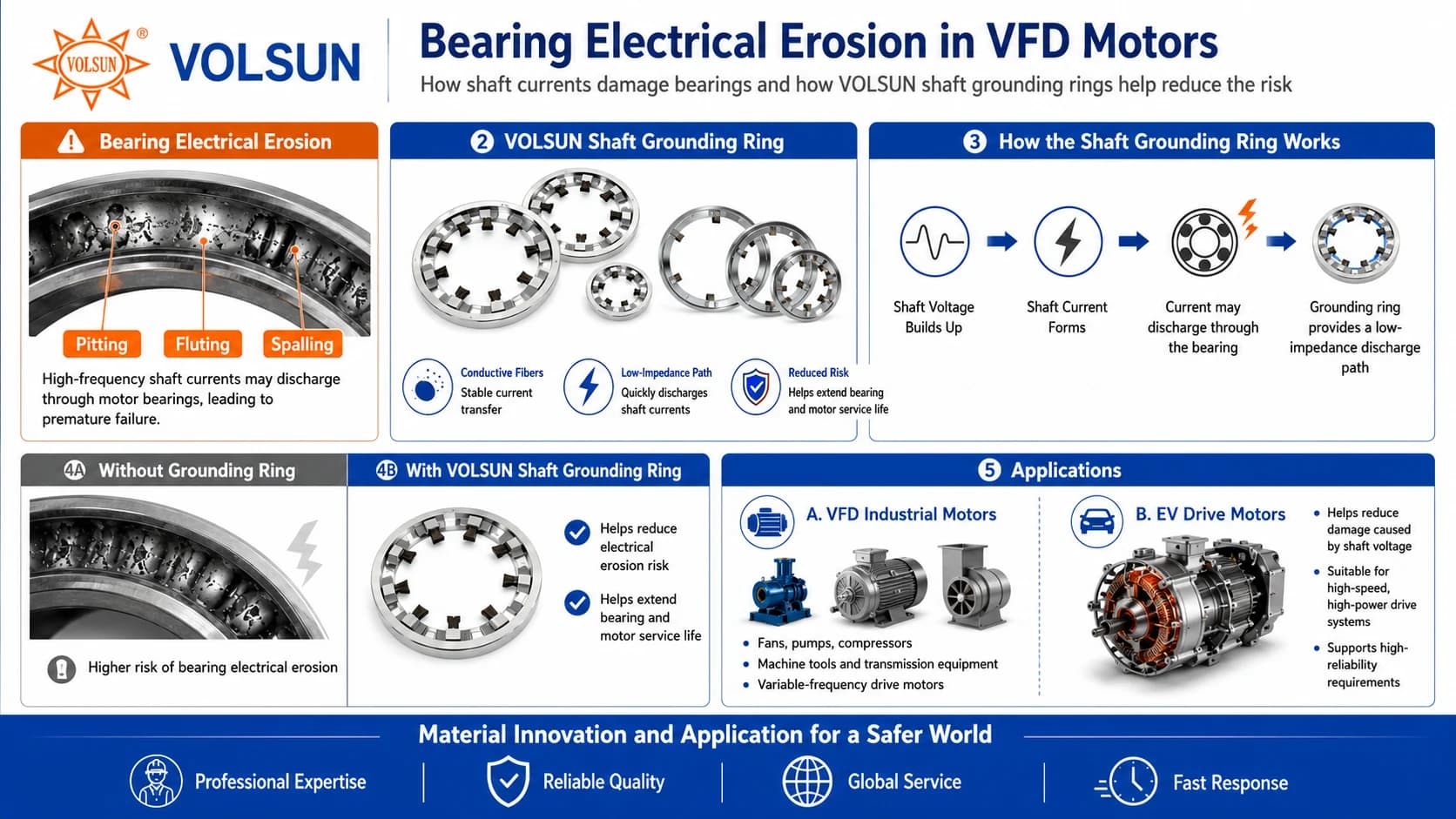
PWM switching in a VFD can generate common-mode voltage that couples capacitively onto the motor shaft. As shaft-to-frame voltage rises, it seeks a path to ground. In many installations, the bearing lubricant film is part of that path. When the voltage exceeds the film’s insulating capability, micro-discharges may occur across the rolling contact.
Each event may be small. Repeated discharges over long operating hours can create surface damage often described as electrical discharge machining (EDM). Over time, this process may contribute to pitting, fluting, higher noise and vibration, and premature bearing failure. Shaft voltage alone does not prove every failure is electrical—but it is a mechanism maintenance teams should evaluate on inverter-fed equipment.
Pitting, Fluting, and Spalling—What the Terms Mean
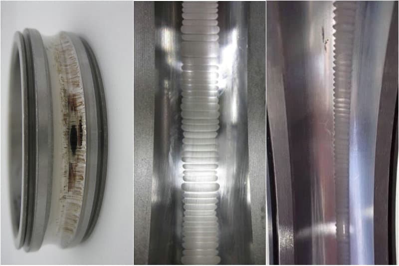
Pitting typically describes localized crater-like marks on rolling surfaces; in an electrical context, pits may form where discharge energy melts microscopic contact zones. Fluting describes a periodic washboard pattern around a raceway and is often associated with repeated electrical discharge under rotation, though visual interpretation still needs supporting evidence. Spalling refers to larger material breakout from fatigue under contact stress and may follow earlier electrical or mechanical surface damage. These terms organize inspection notes—they do not by themselves prove shaft current was the root cause, and late-stage spalling can obscure earlier clues.
Electrical Damage vs. Lubrication and Mechanical Faults
Comparing electrical, lubrication, and mechanical indicators side by side helps prevent automatic attribution of every failure to shaft current. Basic fluting appearance and symptom lists are covered in the companion resource guide; this section focuses on triage for root-cause decisions.
| Observation | More suggestive of electrical erosion | More suggestive of lubrication or mechanical damage |
|---|---|---|
| Raceway appearance | Discrete pits or periodic fluting consistent with discharge under rotation | Spalling, scoring, false brinelling, adhesive wear, or wear bands tied to load zones |
| Operating history | Repeated early failures on VFD-fed motors with similar duty | Failures after contamination, relubrication issues, grease change, or mechanical shock |
| Noise and vibration | Noise that grows with runtime and may correlate with inverter operation | Noise linked to speed, load swings, misalignment, imbalance, or soft foot |
| Lubricant condition | Darkened grease with metallic glitter after possible sparking can occur, but is not proof alone | Water, process contaminant, wrong grease, starved film, or over-greasing |
| System clues | Elevated shaft voltage, long cables, high carrier frequency, weak grounding | Coupling wear, belt tension, overhung load, improper fit, preload or end-play error |
Do not attribute all bearing damage to shaft current. Lubrication film breakdown, wrong grease, water or process contamination, shaft misalignment, incorrect preload or end-play, improper mounting fits, and excessive mechanical load can all produce noise, vibration, pitting-like marks, or progressive raceway damage. Electrical and lubrication factors can also interact—for example, a thin or contaminated film may lower the voltage at which discharge begins—so diagnosis should collect both electrical and mechanical evidence.
For a broader symptom-first overview of fluting appearance and prevention framing, see the resource guide on bearing fluting in electric motors.
Related resource: Bearing Fluting in Electric Motors
Field Diagnostic Workflow for Suspected Electrical Bearing Damage
Use a staged workflow so corrective hardware is not selected from a single photograph or a single vibration reading.
- Document the failure pattern — hours to failure, which end failed, whether the motor is VFD-fed, and whether sister assets show the same history
- Inspect the opened bearing — photograph raceways, rolling elements, cage, and grease condition from multiple angles before cleaning destroys evidence
- Separate electrical clues from lubrication and mechanical clues using the comparison table above
- Review the electrical system — drive type, cable length, bonding, existing insulated bearings or grounding devices, and coupling conductivity
- Measure shaft voltage when safe and practical — after preparation steps below, not as a first improvisation on a running critical asset
- Choose corrective actions only after the likely current path is understood — grounding ring, insulated bearing, common-mode mitigation, or a combination
VFD Bearing Failure Diagnostic Checklist
Before recommending a shaft grounding ring or other mitigation, gather enough application detail for a preliminary review:
- Bearing photographs — raceways, rolling elements, cages, and any fluting or pitting patterns from multiple angles
- Motor and application — frame size, power, speed, duty cycle, driven equipment, and operating hours to failure
- VFD brand and carrier frequency — switching characteristics that may influence common-mode stress
- Cable length — longer motor leads may increase reflected-wave and common-mode effects in some systems
- Shaft voltage waveform — peak-to-peak values and waveform shape when measurement is available
- Probe position and ground reference — where voltage was measured and what reference point was used
- Motor grounding — bonding of frame, conduit, drive cabinet, and any existing grounding devices
- Bearing insulation — whether insulated bearings or ceramic hybrids are already installed
- Coupling and driven equipment — conductive vs insulating couplings and secondary discharge paths
- Lubrication condition — grease type, contamination, moisture, and relubrication history
Incomplete data does not stop a conversation, but it limits how confidently any option can be sized. Application-specific evaluation remains necessary.
How to Prepare for Shaft-Voltage Testing
Shaft-voltage testing is a supporting measurement, not a stand-alone verdict. Preparation improves safety and makes results comparable between motors.
- Confirm lockout/tagout, rotating-machinery clearance, and who may approach the shaft end while the drive is energized
- Identify a clean, accessible shaft surface away from keyways, paint, rust, grease films, and coupling guards that prevent probe contact
- Agree the ground reference — typically the motor frame or a bonded ground point documented in the test note
- Select instrumentation suited to high-frequency content from PWM drives; ordinary low-bandwidth meters can miss the waveform shape of interest
- Record operating condition — speed, load if known, VFD settings, cable arrangement, and whether any shaft grounding or insulated bearing is already fitted
- Photograph probe placement and note drive-end versus non-drive-end access so later reviewers can interpret the reading
Shaft-Voltage Measurement Cautions
There is no single shaft-voltage number that applies to every motor, lubricant film, cable length, and drive setting. Treat readings as context for engineering review.
- Do not invent or rely on a fixed universal threshold from marketing copy; interpret amplitude and waveform with motor construction and bearing condition together
- A low reading at one speed or load does not prove the motor is safe under all operating points
- Probe contact quality, brush bounce, painted shafts, and poor ground references can distort results
- Frame grounding alone does not prove shaft-to-bearing discharge is controlled
- If insulated bearings or a shaft grounding device are already installed, document that before comparing to an unprotected sister motor
- Stop the test if contact cannot be made safely — request a planned outage rather than improvise around guards
Corrective-Action Decision Logic
After electrical risk is plausible, choose actions by the likely current path—not by replacing bearings alone.
- If lubrication or mechanical root causes dominate, correct those first; a grounding ring will not repair contamination, misalignment, or wrong grease
- If shaft-to-ground capacitive discharge is the primary concern, a shaft grounding ring is often evaluated to provide a controlled low-impedance path from shaft to frame
- If circulating bearing current is suspected—especially on larger machines—an insulated bearing on one end is often considered together with shaft grounding on the other
- If common-mode voltage at the motor terminals is severe, review cable length, bonding, filters, or other drive-side mitigation in parallel with shaft-end devices
- If both ends have failed electrically, or OEM guidance calls for a combined architecture, plan coordinated protection rather than a single device
When a Shaft Grounding Ring Is Appropriate
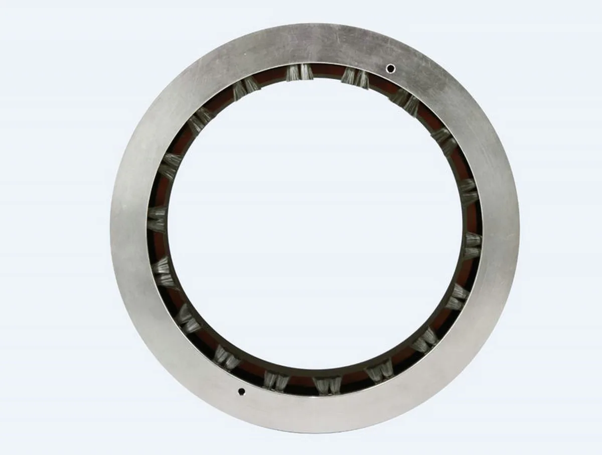
A shaft grounding ring uses conductive microfibers that contact the rotating shaft and connect to the grounded motor frame. It is intended to divert shaft current away from the bearing lubricant film. It does not eliminate all shaft current, and it does not prevent every bearing failure.
- The motor is VFD-fed and shaft-to-ground discharge is a credible mechanism based on history, inspection, or voltage checks
- Bearing damage is consistent with electrical erosion after lubrication and mechanical causes have been reviewed
- A clean shaft contact zone and a reliable path to the grounded frame are available
- Retrofit is preferred without full bearing replacement—arc-shaped rings may be considered when coupling removal is difficult
Mounting must follow the motor end shield, bearing arrangement, speed, environment, and available space. The ring should sit close to the bearing being protected, with conductive fibers maintaining stable contact on a clean shaft surface. Final mounting method is application-specific; this article does not invent a single end-cover geometry for all motors.
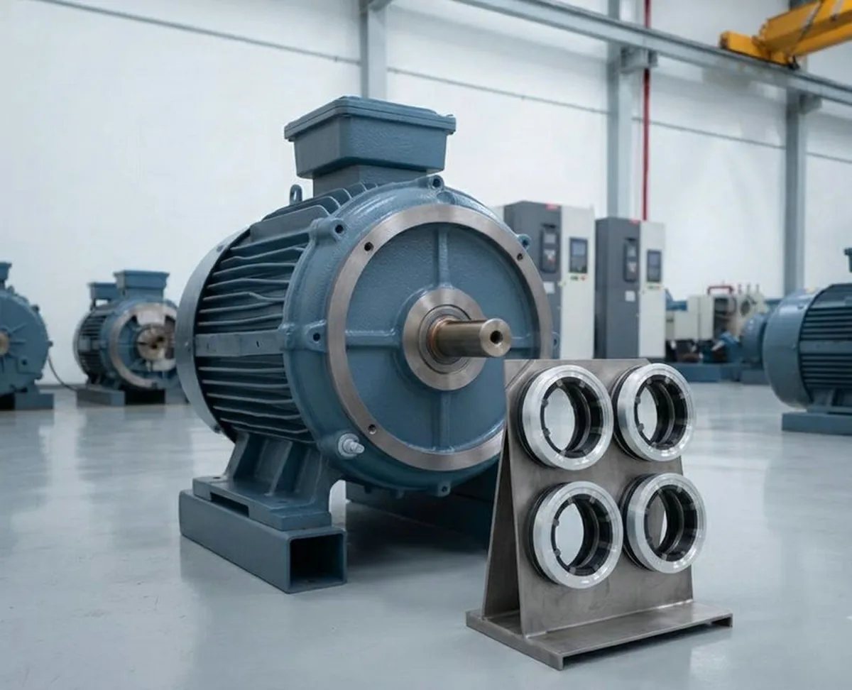
Solid-ring product family: VS-RD/RDW solid shaft grounding ring
Arc-shaped option for constrained retrofits: VS-ST/STW arc-shaped shaft grounding ring
Mounting practice: How to Install a Shaft Grounding Ring Correctly
When Insulated Bearings or Common-Mode Mitigation May Also Be Needed
A shaft grounding ring and an insulated bearing address different parts of the problem. The ring provides a preferred discharge path; an insulated bearing raises the impedance of a specific bearing path. Common-mode mitigation at the drive or cable system can reduce the voltage stress that reaches the motor in the first place. None of these measures is a universal substitute for the others.
- Insulated bearing — useful when circulating current through the shaft–bearing–frame loop is a concern, or when OEM specifications require isolation on one end
- Shaft grounding ring — useful when shaft voltage needs a controlled path to the grounded frame so discharge does not repeatedly traverse the raceway
- Common-mode mitigation — filters, reactors, cable practice, and bonding improvements that reduce common-mode exposure before it appears as shaft voltage
Insulating both bearings without providing a shaft discharge path does not remove shaft voltage; current may seek the coupling or driven equipment instead. For a structured comparison of grounding rings and insulated bearings, see the dedicated article.
Compare protection strategies: Shaft Grounding Ring vs. Insulated Bearing
Engineering Information Required for Product Selection
Catalog shaft diameter alone is not enough. Provide the following so engineering review can match ring type, contact design, and mounting approach to the duty:
- Motor type, frame size, and power rating
- Shaft diameter at the intended contact zone, and maximum RPM
- VFD make/model, carrier or switching information, and approximate motor cable length
- Operating environment — dry, dusty, oil mist, oil-cooled, washdown, or outdoor
- Operating temperature range and available installation space at DE and NDE
- Whether insulated bearings, ceramic hybrids, or existing shaft grounding devices are already fitted
- Shaft-voltage observations, probe location, and any waveform notes
- Bearing-damage symptoms and photographs when available
Selection input framework: How to Select a Shaft Grounding Ring for EC and VFD Motors
Industrial Dry Motors vs High-Speed or Oil-Cooled EV Motors
Shaft diameter is a necessary dimensional input, but it is not a complete sizing rule. An industrial dry-frame motor and a high-speed EV traction motor with oil mist or oil-chamber cooling may share a similar shaft diameter while differing in speed profile, lubricant exposure, packaging envelope, grounding architecture, and duty cycle. Oil films can disrupt fiber-to-shaft contact; high peripheral speeds change wear and contact stability; compact EV housings may leave little room for a catalog ring. Industrial dry motors and oil-cooled or high-speed EV drive motors therefore require application-specific evaluation rather than selection by shaft diameter alone.
For traction-motor context, read: Why EV Drive Motors Need Shaft Current Protection
Practical Takeaways
VFD motors may develop shaft voltage that discharges through bearings and contributes to pitting, fluting, and premature failure. Treat electrical erosion as one plausible mechanism among lubrication and mechanical causes. Follow a field diagnostic workflow, prepare carefully for shaft-voltage checks, and choose corrective actions by current path—shaft grounding ring, insulated bearing, common-mode mitigation, or a coordinated combination. If your team sees repeated VFD motor bearing failures, gather the engineering inputs above and request a preliminary application review before ordering from catalog diameter alone.
Need Help Diagnosing Repeated VFD Motor Bearing Failure?
Send us your bearing inspection photos, shaft diameter, motor speed, VFD information, operating environment, and available installation space for a preliminary application review.
Submit Motor Requirements