How to Install a Shaft Grounding Ring Correctly: Five Critical Checks
|
A practical installation guide covering shaft preparation, conductive-fiber contact, ring alignment, frame grounding, common installation errors, and post-installation verification.
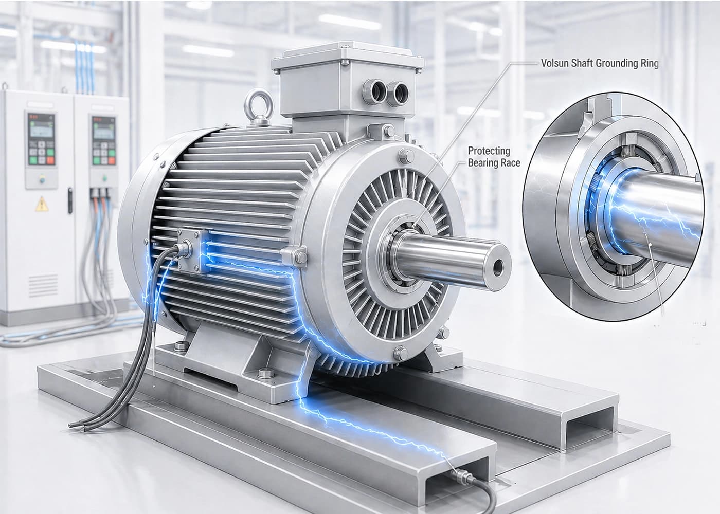
Why Installation Quality Matters
A shaft grounding ring is intended to help provide a controlled low-impedance path from the rotating shaft to the grounded motor frame. Installation quality strongly influences whether that path remains stable in service. Poor surface preparation, uneven fiber contact, or an incomplete frame bond may leave bearings as an unintended discharge route, even when a ring is fitted.
This guide focuses on installation practice—not on a full explanation of VFD shaft-voltage theory. For diagnosis of repeated bearing damage, see our article on diagnosing repeated VFD motor bearing failure. For product family selection inputs, use the shaft grounding ring selection guide before mounting work begins.
Related reading: diagnosing repeated VFD motor bearing failure
Before you mount a ring, review: shaft grounding ring selection guide
Before Installation: Confirm the Motor and Mounting Conditions
Confirm the motor type, shaft diameter at the intended contact zone, available axial and radial space, access for tools, and whether the end shield or bearing housing can accept the approved mounting method. Record nameplate data, maximum speed, duty cycle, and the operating environment—dry industrial, dusty, oil-mist, or oil-cooled—because environment may change which structure is suitable.
Also confirm grounding architecture: how the motor frame is bonded, whether insulated bearings are present, and whether couplings or driven equipment may create secondary paths. Mechanical clearance alone is not enough. Application-specific review may be required when drawings, photos, or access constraints leave uncertainty.
Five Critical Installation Checks
Use the following five checks as the core installation sequence. They apply to solid-ring mounting on many industrial VFD motors; constrained-access arc-shaped installations have additional packaging considerations covered in the arc-shaped shaft grounding ring installation guide.
For ST/STW access-limited mounting, see: arc-shaped shaft grounding ring installation guide
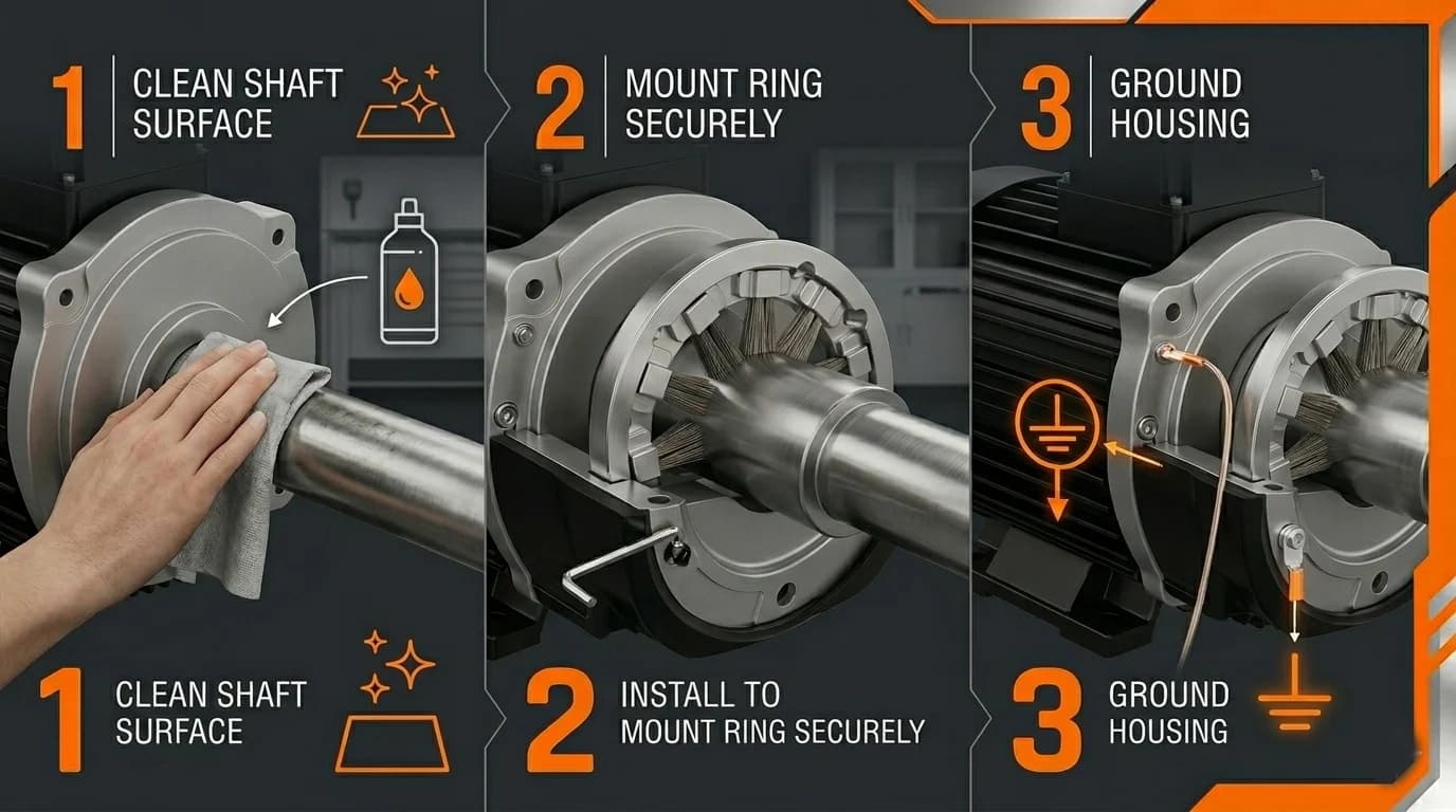
The overview image below shows three basic actions—cleaning the shaft, mounting the ring with fiber contact, and grounding the housing. It is a simplified three-step overview, not a complete five-check diagram, and it is not a precise engineering drawing. Continuity, interference, and operating checks should still follow after installation. Always follow the specific motor structure and approved installation requirements for the product in use.
1. Prepare a Clean Shaft Contact Zone
Remove paint, rust, oil, dust, and non-conductive contamination from the contact zone. Conductive fibers should contact a continuous and suitable shaft surface. A film of paint, oxide, grease, or process residue may raise impedance and make contact unstable. After cleaning, protect the prepared zone from recontamination until the ring is mounted.
2. Confirm the Correct Contact Position
Locate the contact band where fibers can ride on a continuous cylindrical surface. Avoid keyways, threads, sharp shoulders, deep grooves, and discontinuous surfaces. If the only available band is interrupted, stop and request an application-specific installation review rather than forcing contact over an unsuitable geometry.
3. Maintain Even Fiber Contact and Alignment
Ring alignment and fiber contact should be even around the circumference. Seat the ring so conductive fibers engage the shaft consistently without local gaps or crushing. Fasteners should be tightened evenly without distorting the ring body. Uneven pressure may cause intermittent transfer and accelerated local wear. Re-check concentricity after final torque.
4. Verify the Grounding Path to the Motor Frame
The ring body or mounting bracket must have a reliable electrical connection to the grounded motor frame. Mechanical mounting alone does not prove electrical continuity. Confirm bonding through the bracket, fasteners, or dedicated ground lead as specified for the design. A ring that is mechanically secure but electrically isolated from frame ground cannot perform its intended function.
5. Inspect and Verify After Installation
After mounting, inspect fiber engagement, fastener security, and clearances. Check for interference while rotating the shaft according to an approved safe procedure. Where suitable equipment and procedures are available, compare shaft-voltage results using the same probe position, grounding reference, instrument bandwidth, load, speed, and operating condition. Verification helps reduce the risk of leaving an incomplete path in service; it does not prove that every operating condition is covered.
For the full measurement procedure, including probe placement, oscilloscope setup, and before/after comparison: How to Measure Shaft Voltage in VFD Motors
Product family often reviewed for industrial VFD motors: VOLSUN solid shaft grounding rings
Five Common Installation Errors
The table below summarizes frequent field errors and corrective actions. Treat it as a practical checklist, not as a complete failure-mode catalog.
| Installation Error | Possible Consequence | Corrective Action |
|---|---|---|
| Installing over paint, rust, oil, or contamination | Unstable or high-impedance contact | Clean and prepare the shaft contact zone |
| Uneven fiber contact or poor alignment | Intermittent current transfer and uneven wear | Recheck concentricity, alignment, and mounting position |
| Ring body not electrically bonded to frame ground | Incomplete discharge path | Verify grounding continuity to the motor frame |
| Contact over a keyway, thread, groove, or sharp edge | Interrupted contact or accelerated fiber wear | Move the contact zone to a continuous shaft surface |
| Ignoring speed, temperature, or lubrication environment | Unsuitable material or mounting structure | Request an application-specific installation review |
Post-Installation Verification Checklist
Complete these checks before returning the motor to unsupervised operation. Results depend on the application and available test methods.
- Ring body and bracket remain secure
- Conductive fibers contact the shaft evenly
- No mechanical interference is observed
- Grounding continuity to the motor frame is verified
- Shaft-voltage measurements, when performed, use the same test setup before and after installation
- Installation position, motor data, and photos are recorded for maintenance
- Noise, vibration, and bearing condition are monitored during subsequent operation
Successful verification should not be described as eliminating all shaft current or guaranteeing zero bearing failure. It confirms that the installed path and mounting condition look acceptable under the checks that were actually performed.
Industrial Dry Motors vs. Oil-Mist or Oil-Cooled Motors
Industrial dry motors usually emphasize shaft cleaning, dust control, mounting envelope, and maintenance access. Oil-mist or oil-cooled applications require a fresh review of materials, fiber structure, sealing, contamination, and lubricant exposure. Do not assume that the same conductive-ring structure is suitable for both dry and oil-cooled environments. Different environments may need different structures or an application-specific installation review.
For industrial application context, see: industrial motor shaft grounding applications
When to Request an Application-Specific Installation Review
Request a review when shaft geometry is non-catalog, access prevents standard mounting, the environment includes oil mist or immersion, speed or thermal duty is unusual for the selected structure, insulated bearings or complex grounding already exist, or photos and drawings leave doubt about contact position. Provide motor drawings, shaft diameter, installation photos, maximum speed, operating environment, and available mounting space so engineers can assess fit before parts are ordered or remounted.
Conclusion
Correct installation helps provide a usable discharge path and helps reduce the risk of leaving bearings as the only route for shaft current. Focus on a clean continuous contact zone, even fiber engagement, reliable frame bonding, and verified post-installation checks. When conditions fall outside standard dry-motor mounting practice, stop and request an application-specific installation review rather than forcing a catalog fit.
Need Help Reviewing Your Shaft Grounding Ring Installation?
Send us your motor drawing, shaft diameter, installation photos, maximum speed, operating environment, and available mounting space for a preliminary installation review.
Request an Installation Review