Split Shaft Grounding Ring Retrofit: Engineering Considerations for Assembled Motors
|
An engineering-focused review of retrofitting a split shaft grounding ring on an assembled motor, using a paper mill project as reference background.

When a motor cannot be pulled from its driven equipment, retrofitting shaft-grounding protection becomes an engineering question before it becomes a product selection. In August 2026, VOLSUN delivered and installed a custom split shaft grounding ring on a large industrial motor at a paper mill, where the machine had to stay in place. This article uses that project as reference background and concentrates on the engineering considerations that decide whether such a retrofit is sound: mounting space, shaft-surface contact, fixing method, conductive path, fit parameters, and trial-run validation.
Related project background: paper mill split shaft grounding ring project (VOLSUN group site)
What the Reference Project Establishes
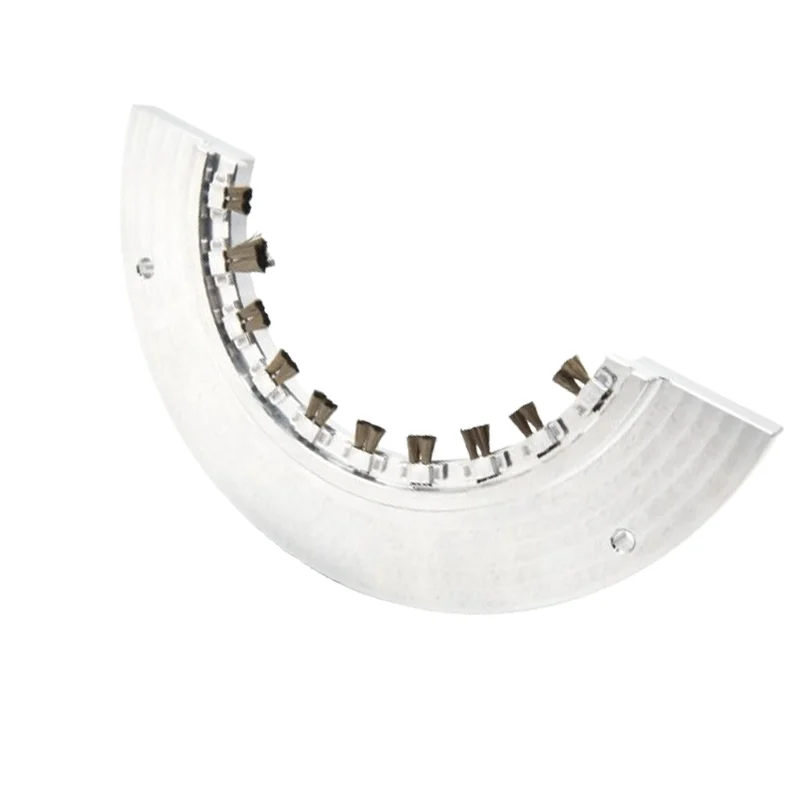
The paper mill motor runs in a 24/7 production environment, combines high power with low rotational speed, and was already fully assembled when the plant's engineers contacted VOLSUN. The ring supplied was a split-type design built around conductive carbon fiber contact, with adjustable brackets and bolts for fixing to the motor housing. Delivery and on-site installation were completed in August 2026. As of this writing, the ring is undergoing live testing on the customer's motor, and final performance feedback from the plant is still pending. No service-life, durability, or bearing-protection figures are claimed for this project, and none should be inferred.
Engineering Checklist for an Assembled-Motor Retrofit
The following checks are general engineering practice for evaluating a split-ring retrofit on an assembled motor. They are not results from the reference project, and they do not replace an application-specific review.
- Installation space and access — map the axial and radial envelope at the intended mounting zone, including tool access and clearance for the ring halves. Tight access changes the mounting sequence and preparation work; it does not by itself decide feasibility.
- Shaft surface and contact zone — identify a continuous cylindrical band on the shaft for fiber contact. Keyways, threads, shoulders, and grooves interrupt the surface, and paint, oxide, or grease films can destabilize contact. Where the only available band is interrupted, stop and request an application-specific review.
- Fixing method and alignment — review how the ring will be secured to the motor housing. Adjustable brackets accommodate real housing geometry, and alignment with the shaft centerline matters because uneven seating leads to uneven fiber contact.
- Conductive path — the ring is designed to offer shaft current a controlled path to the motor frame instead of the bearings. Whether that path performs as intended in a specific machine is exactly what field validation is meant to check.
- Fit parameters — collect the data an engineering review needs: shaft diameter at the contact zone, rated and maximum speed, power rating, VFD details, duty cycle, environment (dust, oil mist, humidity), and the existing grounding architecture, including any insulated bearings.
- Trial-run validation plan — define in advance what will be observed during live running and over what period. Installation completion is a hardware milestone, not a performance verdict.
What a Trial Phase Can and Cannot Confirm
A retrofit that is mechanically complete has cleared the installation risk, not the performance question. Live testing under the customer's real duty cycle is what shows whether the contact path stays stable and whether the mitigation behaves as intended in that machine. The reference project is in exactly this phase, which is why this article reports no performance outcome for it. Projects at this stage should be described as installed and under validation — not as verified.
Preparing an Engineering Review
Retrofit decisions improve when the plant's motor data reaches the engineering review early: power rating, shaft diameter, rotational speed, VFD information, installation envelope, operating environment, and photos or drawings of the mounting area. With those inputs, suitability can be assessed before any hardware is committed. For step-by-step mounting practice, use the installation guides linked below.
Related resources: Arc-Shaped (ST/STW) Shaft Grounding Ring — Product Overview
arc-shaped shaft grounding ring installation guide
how to install a shaft grounding ring correctly: five critical checks
Background theory: what causes shaft voltage in VFD motors
Conclusion
Bearing-current protection has to fit the machine that is already installed. For assembled motors where teardown is not an option, the split-ring route is an engineering decision to be validated — space, contact, fixing, path, fit data, and a defined trial. If your facility faces a similar constraint, send your motor data to the VOLSUN engineering team for a preliminary application review.
Facing Bearing-Current Issues Without the Option of Teardown?
Send us your motor data: power rating, shaft diameter, rotational speed, VFD information, installation envelope, and operating environment. VOLSUN's engineering team can review whether a split shaft grounding ring suits your layout and outline the validation steps involved.
Submit Your Motor Application Data