How to Measure Shaft Voltage in VFD Motors: Test Setup, Waveforms and Grounding Verification
|
A field procedure for measuring shaft voltage on VFD motors: probe placement, ground reference, waveform capture, before/after shaft-grounding checks, and the data needed for engineering review.
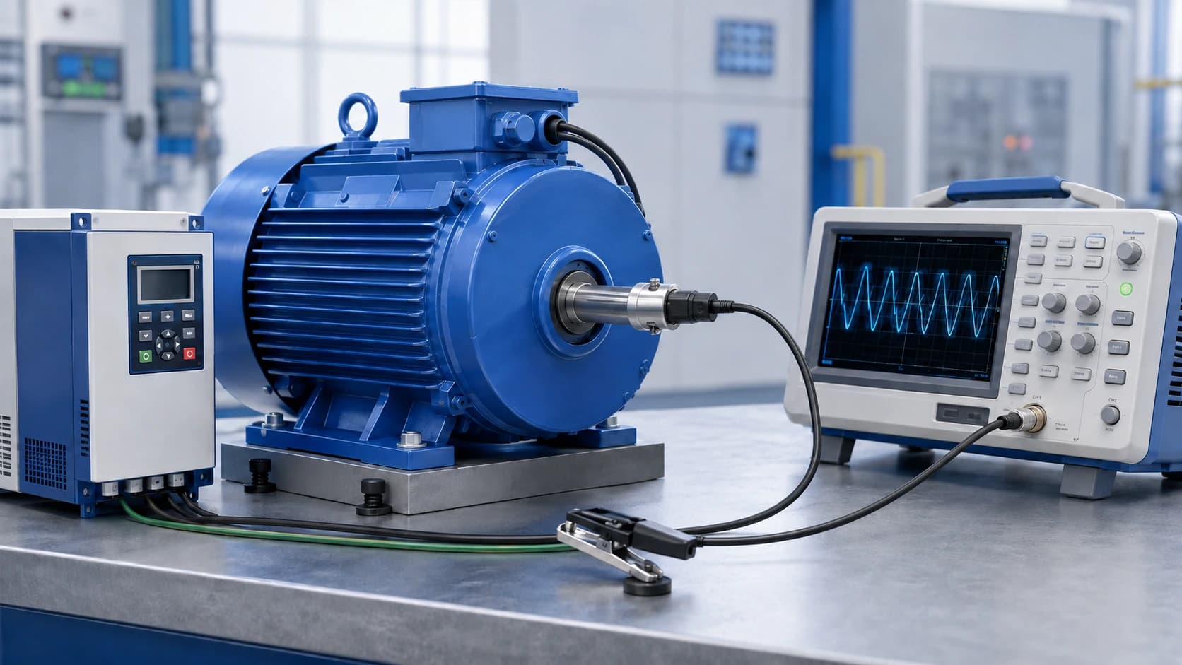
Shaft voltage measurement is the practical next step after you already understand what shaft voltage is. It answers a different question: under this motor, this drive, and this grounding arrangement, what voltage appears on the shaft, and how does that waveform change after a controlled shaft-to-frame path is installed?
This guide is a measurement and interpretation procedure. It does not re-explain VFD shaft-voltage theory, and it does not select a shaft grounding ring from a single peak reading. For the mechanism, start with the shaft-voltage primer. For product family inputs, use the selection guide. For mounting practice, use the installation guide.
If you need the mechanism first: What Is Shaft Voltage
If you already have a waveform and need product-family inputs: How to Select a Shaft Grounding Ring
Quick Answer
Measure shaft voltage with a high-bandwidth instrument, a stable shaft contact, and a documented motor-frame ground reference. Record the operating condition. Capture waveform shape, not only a peak number. Repeat the same setup after installing a shaft grounding ring if you are checking that path. There is no single shaft-voltage threshold that applies to every motor and VFD system. Use the result as one input for engineering review, together with bearing arrangement, grounding, cable system, and actual bearing condition.
Why Measure Shaft Voltage on a VFD Motor?
A VFD’s PWM output can produce common-mode voltage at the motor. Capacitive coupling can then place voltage on the rotor and shaft. Shaft voltage is that electrical stress on the rotating shaft relative to a chosen reference, usually the motor frame. Bearing current is a different quantity: it is current that actually flows through a bearing path. Electrical discharge machining (EDM) is one possible result when voltage across the lubricant film breaks down and a brief discharge occurs.
These four terms are related, but they are not interchangeable:
- Common-mode voltage — drive-side electrical stress that can couple into the motor
- Shaft voltage — voltage observed on the shaft relative to a documented reference
- Bearing current — current through a bearing path, which a voltage probe does not measure directly
- EDM discharge — a brief breakdown event that may appear as a spike on a shaft-voltage waveform
Measurement is useful when you need a comparable record: a suspected electrical bearing problem, a before/after check after installing a shaft grounding ring, or application data for an engineering review. A waveform does not, by itself, prove that a ring must be fitted, and a low reading at one operating point does not prove the motor is electrically quiet under all conditions.
For diagnosis of repeated bearing damage rather than the test method: What Causes VFD Bearing Failure?
What Equipment Is Needed?
The goal is to capture high-frequency content from PWM switching and, where present, short discharge events. A handheld low-bandwidth meter can miss the waveform shape that matters for review.
- Oscilloscope with enough bandwidth and sample rate to show PWM switching and brief spikes, not only a 50/60 Hz envelope
- Shaft contact method — a purpose-built shaft-voltage probe, a conductive brush, or another approved contact that can ride a clean shaft surface without damaging it
- Ground lead to a documented motor-frame or bonded-frame reference
- Means to record operating condition — speed, load if known, VFD settings, and whether a grounding device or insulated bearing is already fitted
- Camera or screen capture for the waveform and for probe position
- Approved rotating-machinery safety controls — lockout/tagout, guards, and a procedure that allows shaft access only when the plant permits it
Do not treat a specific bandwidth number, probe brand, or sampling setting as a universal VOLSUN laboratory specification. Instrument choice should match the switching content you expect and the safety rules of the site. If contact cannot be made safely, stop and plan a controlled outage rather than improvise around guards.
Basic Shaft Voltage Measurement Setup
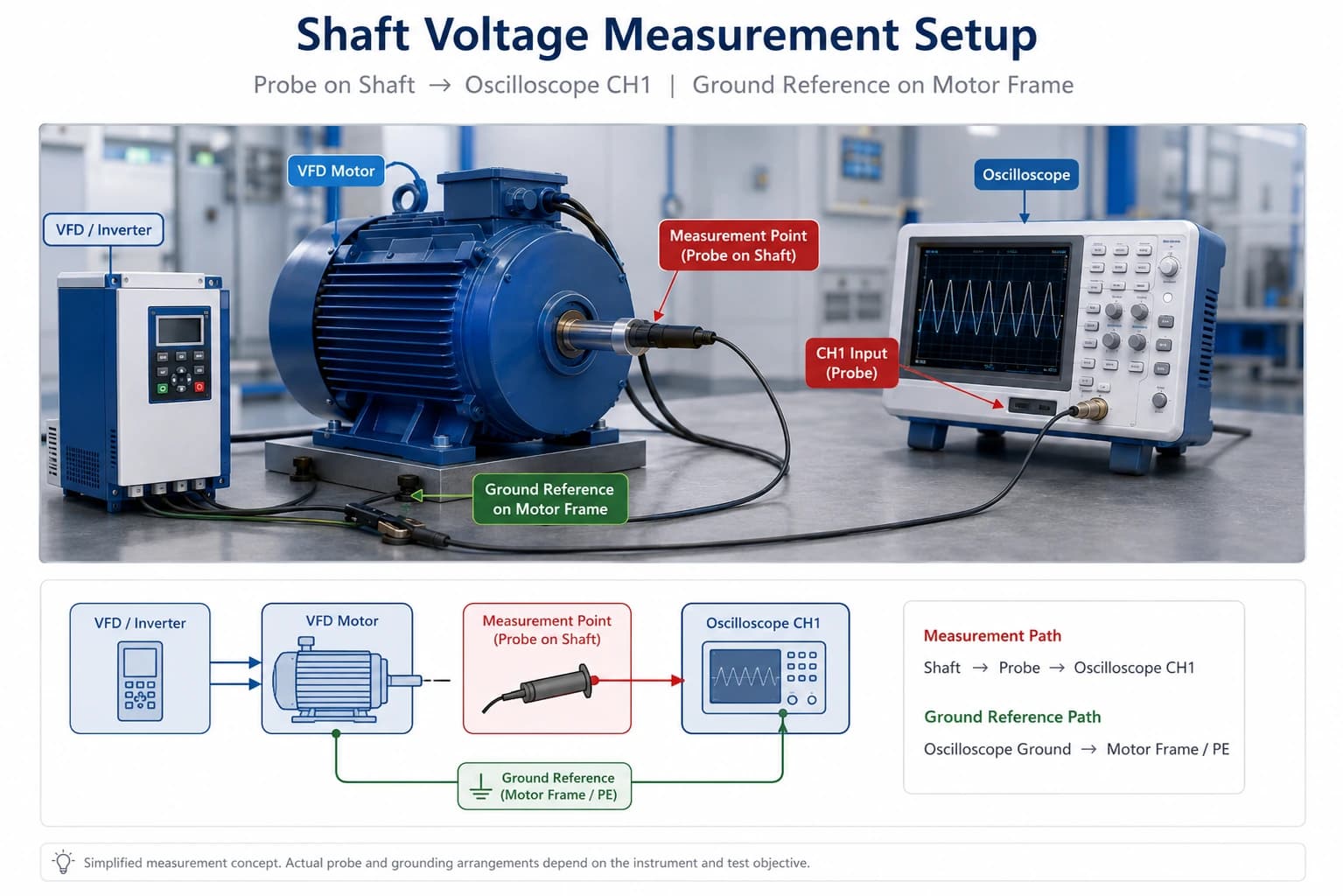
The electrical chain is simple: shaft contact → probe or brush → oscilloscope channel → ground reference on the motor frame. The quality of that chain is not simple. Unstable shaft contact, a painted or greasy shaft, a long unsecured ground lead, or a reference taken from a distant cabinet can all change the displayed voltage without changing the motor.
Before energizing, agree and write down:
- Which shaft end is contacted — drive end or non-drive end
- Where the probe or brush sits on the shaft
- Which point is the ground reference
- Oscilloscope coupling, time base, vertical scale, bandwidth limit, and sampling setup
- Motor speed, load, and VFD operating mode for this run
Treat the setup as a documented chain: shaft contact, instrument, and frame reference must all be written down before the first screenshot. Changing any link in that chain later makes the waveform hard to compare.
Where Should the Probe and Ground Reference Be Connected?
Contact a clean, continuous cylindrical shaft surface. Avoid paint, rust, grease films, keyways, threads, coupling guards, and damaged zones. Drive-end access is common, but non-drive-end access may be the only safe or mechanically possible point. Record which end you used; the two ends are not automatically equivalent when insulated bearings, couplings, or existing grounding devices are present.
The ground reference should be the motor frame or another bonded point that represents the frame for this test. Do not silently change from frame to conduit, from frame to drive cabinet, or from one bolt to an unbonded cover between runs. A changed reference is a different measurement.
Keep the ground lead short and mechanically secure where the site allows it. A long looping lead can pick up radiated switching noise that is not shaft voltage. Photograph the probe position and the reference clamp so a later reviewer can interpret the screenshot.
Step-by-Step Shaft Voltage Measurement
Use a staged procedure so later comparisons remain valid. The six steps below are a field sequence, not a substitute for the plant’s electrical-safety rules.
Step 1. Record Motor / VFD Operating Conditions
Write down motor type, power, rated and maximum speed, VFD model and relevant settings if known, cable arrangement if visible, bearing configuration if known, and existing grounding or insulation hardware. Note speed and load for this test. A waveform without operating context cannot be compared with a later test.
Step 2. Prepare the Shaft Measurement Point
Select a clean, accessible band. Remove only the contamination that prevents electrical contact, using a method approved for that shaft finish. Do not grind a new surface as a casual field fix. If the only exposed metal is a keyway edge or a painted shoulder, the contact is not a valid shaft-voltage point.
Step 3. Connect the Measurement Setup
Fit the probe or brush so contact is stable at the intended speed. Bond the instrument ground to the agreed frame reference. Set the oscilloscope so both switching-period content and brief spikes can be seen. Save the instrument setup or photograph the front panel. Do not change coupling, bandwidth, or scale later unless you document the change as a new test.
Step 4. Run the Motor Under Defined Operating Conditions
Bring the motor to the recorded speed and load. If the plant can only run unloaded, say so in the note. Do not compare an unloaded shop test with a loaded process condition as if they were the same measurement. If several speeds matter in service, treat each speed as its own run.
Step 5. Capture Waveform / Peak Behavior
Save at least one screenshot that shows the repetitive PWM-related shape and, if present, discharge spikes. Note peak or peak-to-peak values only as a supplement to the image. A single cursor reading without shape, time base, and operating condition is weak evidence. If spikes are intermittent, capture more than one event and say so.
Step 6. Document the Measurement Setup
Record probe position, ground-reference location, instrument settings, motor and VFD identity, operating condition, and whether a shaft grounding ring or insulated bearing was already fitted. Keep the waveform file with that note. A screenshot without setup data is difficult to review and easy to misread.
Measure Before and After Installing a Shaft Grounding Ring
A before/after pair is useful only when the two runs are the same test. After mounting a ring, keep all of the following unchanged:
- Motor speed
- Load condition
- Probe position
- Grounding reference
- Oscilloscope settings
- Bandwidth and sampling setup, where those controls apply
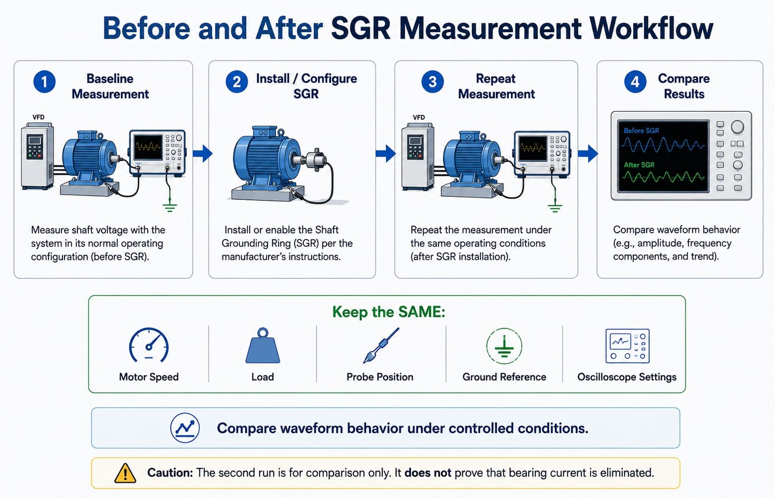
If any of those items change, you no longer have a before/after comparison; you have two different tests. Installation quality still matters: a ring that is mechanically fitted but not bonded to frame ground cannot be judged by a voltage screenshot. For mounting checks, use the installation guide rather than treating the waveform as a complete installation audit.
Post-installation mechanical and bonding checks: How to Install a Shaft Grounding Ring
A lower shaft-voltage display after installation suggests that a lower-impedance shaft-to-frame path is present under that specific condition. It does not prove that every bearing current path is controlled, that circulating current is absent, or that bearings will not fail from lubrication or mechanical causes.
How to Interpret a Shaft Voltage Waveform
Do not judge the motor from one peak-voltage number. Read the waveform as a set of clues:
- Waveform shape — switching-period content versus a slow envelope
- Repetitive discharge spikes — possible EDM events, not proof by themselves
- Switching behavior — alignment with VFD PWM rather than random pickup
- Grounding reference — whether the displayed voltage is shaft-to-frame or something else
- Instrument bandwidth — whether spikes could have been filtered out or exaggerated by poor probing
- Motor operating condition — speed, load, and whether protection hardware was already fitted
A conceptual PWM envelope with occasional sharp spikes is often discussed as a signature of switching stress plus film breakdown. Treat published sketches as conceptual. They are not a substitute for the screenshot you captured on the actual motor.
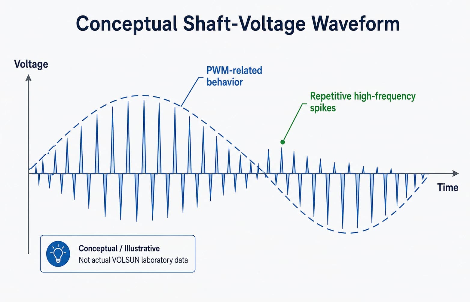
Shaft voltage is not bearing current. A high shaft voltage can exist with little bearing current if the film holds or another path dominates. A lower shaft voltage can still accompany damaging current if the path through a bearing remains the easiest route. Common-mode current in the cable system is a third measurement and should not be inferred from a shaft probe alone.
Is There a Safe Shaft Voltage Threshold?
There is no single shaft-voltage threshold that applies to every motor and VFD system. Lubricant-film breakdown depends on film thickness, speed, temperature, bearing design, and the high-frequency content of the voltage, not on a marketing number copied from one machine to another.
Judgement should combine:
- Motor construction
- Bearing arrangement, including any insulated bearing
- VFD topology and switching
- Grounding of the motor and driven equipment
- Cable system
- Available shaft-current paths
- Actual bearing condition — noise, vibration, grease, and raceway appearance when inspection is possible
VOLSUN does not publish a universal “safe volts” figure for all VFD motors, and this article does not invent IEC, IEEE, or NEMA limit values. If a project specification cites a numbered criterion, use that project’s document. Do not treat it as a global rule.
Five Common Shaft Voltage Measurement Mistakes
| Mistake | What goes wrong | What to do instead |
|---|---|---|
| Inconsistent grounding reference | The displayed voltage is no longer shaft-to-frame | Clamp the same bonded frame point for every run and photograph it |
| Unstable shaft contact | Bounce, paint, or a keyway edge creates false spikes or dropouts | Use a clean continuous band and a contact method that stays seated at speed |
| Changing test conditions | Speed, load, or VFD mode changes are mistaken for a grounding effect | Hold operating condition constant, especially for before/after pairs |
| Insufficient instrument bandwidth | PWM edges and EDM spikes are filtered into a misleading envelope | Use an instrument and settings that can show switching and brief events |
| Evaluating voltage without reviewing current paths | A peak number is treated as a complete diagnosis | Review bearings, couplings, frame bonding, cables, and existing protection with the waveform |
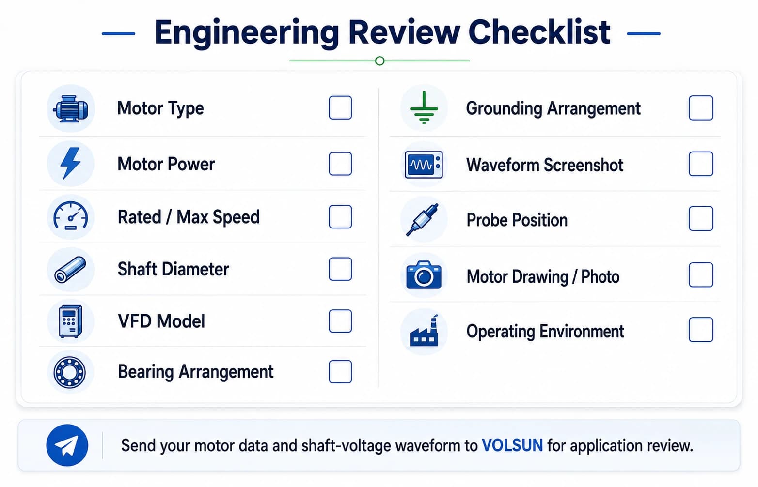
What Data Should You Send for Engineering Review?
A waveform is more useful when the application around it is visible. Send as much of the following as you can:
- Motor type
- Motor power
- Rated / maximum speed
- Shaft diameter
- VFD model if known
- Bearing configuration
- Grounding arrangement
- Waveform screenshot
- Probe position
- Motor drawing / photo
- Operating environment
Have a shaft-voltage waveform?
Send us a waveform screenshot, motor nameplate data, shaft diameter, VFD information, and bearing arrangement for an application review. Incomplete packages still start a conversation; they only limit how specific the first comment can be.
Send shaft-voltage data for application review
How Shaft Grounding Rings Fit Into the Diagnosis
A high measured shaft voltage is not, by itself, an instruction to install a shaft grounding ring. A ring provides a controlled shaft-to-frame discharge path through conductive-fiber contact. Whether that path is the right next step depends on the rest of the current map: insulated bearings, couplings, driven equipment, cable common-mode paths, and whether circulating bearing current is also plausible.
On many industrial VFD motors, a solid shaft grounding ring is reviewed as one way to offer that controlled path. It does not eliminate all bearing current, and it does not guarantee that bearings will not fail. Installation quality, shaft surface, and frame bonding still decide whether the intended path exists in service.
Solid ring product family often reviewed for industrial VFD motors: Solid Shaft Grounding Ring
When circulating current or an insulated bearing is also in play: Shaft Grounding Ring vs Insulated Bearing
Conclusion
Shaft-voltage testing is a documented procedure: same contact, same reference, same instrument settings, same operating condition. Read waveform shape and discharge behavior together with the motor’s current paths. Do not convert one peak reading into a universal safe limit, and do not treat a lower voltage after fitting a ring as proof that every bearing risk is gone.
Send us your shaft-voltage waveform and motor data for an application review.
Have a Shaft-Voltage Waveform?
Send us a waveform screenshot, motor nameplate data, shaft diameter, VFD information, bearing arrangement, probe position, and operating environment. VOLSUN’s engineering team will review the application. A high reading is not, by itself, an instruction to install a shaft grounding ring.
Send Shaft-Voltage Data for Review