When Standard Shaft Grounding Rings Are Not Enough: 6 Cases That May Need Custom Design
|
A practical review of when a standard shaft grounding ring may fit—and when shaft geometry, space, speed, oil exposure, mounting, or OEM validation may require a custom design review.
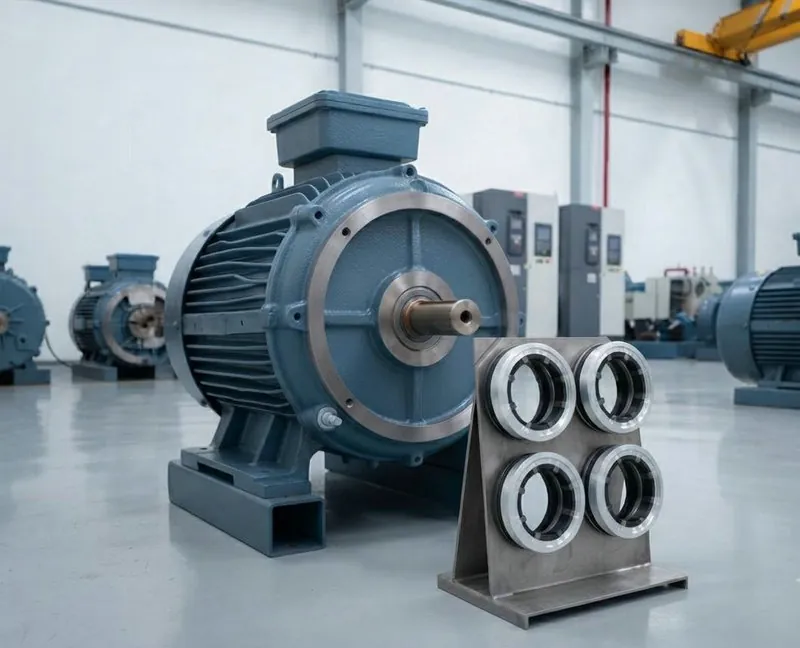
Standard Rings Work for Many Motors—But Not Every Application
A standard shaft grounding ring can be a practical solution when shaft size, mounting space, speed, operating environment, and grounding architecture fall within the intended design window. In those cases, a standard solid or arc-shaped ring may help provide a controlled current path away from the motor bearings without a custom development program.
Problems begin when a grounding ring is selected by shaft diameter alone. Diameter is a necessary input, but it does not describe tolerance at the contact zone, available contact width, runout, radial and axial clearance, mounting access, lubricant exposure, or OEM validation expectations. When those factors sit outside the intended standard design window, an application-specific review—and in some cases a custom shaft grounding ring design—should be evaluated.
Customization is not automatically better. The useful sequence is standard solution → application review → custom design only when needed.
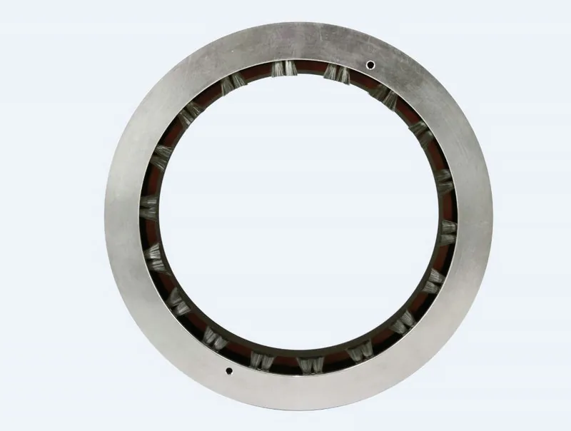
Six Cases That May Require Custom Design
Unusual Shaft Diameter or Tolerance
Shaft diameter is usually the first dimensional check, but it is rarely enough for a reliable fit review. Tolerance at the intended contact position, available contact width, shaft runout, and the exact contact location along the shaft all influence whether conductive fibers can maintain stable engagement under rotation.
A ring matched only to a nominal diameter may still be unsuitable if the contact zone is too narrow, sits on a shoulder or damaged surface, or operates with runout that challenges continuous fiber contact. When drawings or measured data show non-standard geometry, the design should be reviewed before assuming a standard size is adequate. Diameter alone is not enough.
Limited Radial or Axial Installation Space
Installation envelope often decides whether a standard structure is realistic. Limited radial space, limited axial depth, nearby seals, or retrofit access constraints may prevent a continuous solid ring from seating correctly or from being fastened without distorting the housing.
In constrained envelopes, a split shaft grounding ring (arc-shaped structure) may be more suitable because it can simplify mounting where full circumferential access is difficult. In other cases, a mounting bracket, revised fastening pattern, or a custom envelope may need review. The point is not that every tight motor requires custom tooling—it is that space and access should be evaluated before a standard part is ordered.
Compare standard solid structures: VOLSUN solid shaft grounding rings
When access is constrained, review an arc-shaped option: split shaft grounding ring
For mounting checks, see the: shaft grounding ring installation guide
High-Speed Motor Applications
Higher rotational speed may change requirements for conductive fiber contact stability, concentricity, mounting rigidity, wear behavior, and validation. Peripheral speed, duty cycle, and how the ring is fixed to the housing can all affect whether contact remains consistent in service.
That does not mean high-speed motors always require a custom ring. Many applications may still be served by a standard configuration after the speed profile and mounting conditions are reviewed. When speed, packaging, and duty sit outside typical standard assumptions, an application-specific review should be completed before design or production decisions are locked. No universal RPM boundary replaces that review.
Oil-Mist or Oil-Cooled Environments
A design suitable for a dry industrial motor should not automatically be assumed suitable for an oil-cooled motor. Lubricant exposure, oil mist, contamination, material compatibility, mounting structure, and conductive contact stability under oil film conditions may all require a fresh evaluation.
Oil or lubricant films may change conductive contact behavior between the fibers and the shaft. Material compatibility, contamination, flow conditions, and contact stability should therefore be evaluated for the actual application. For oil-mist or oil-cooled duty, material choice, fiber arrangement, and mounting should be reviewed against the actual lubricant and flow conditions—and application-specific validation may be required. Suitability depends on the operating conditions; no single ring design should be claimed to work in all oils or to maintain contact under every oil condition.
For broader application context, see: industrial motor shaft grounding applications
For electrified drive packaging context, see: EV motor shaft grounding applications
For detailed electrical and mechanical selection inputs, see the: shaft grounding ring selection guide
Non-Standard Mounting or Motor Geometry
End shields, bearing housings, shaft shoulders, seals, restricted fastening positions, and retrofit geometry can all push a project outside a standard mounting interface. In those cases, the question is not only “which size,” but whether the ring can be located on a suitable shaft contact zone and bonded to the intended ground path without conflicting with seals or other hardware.
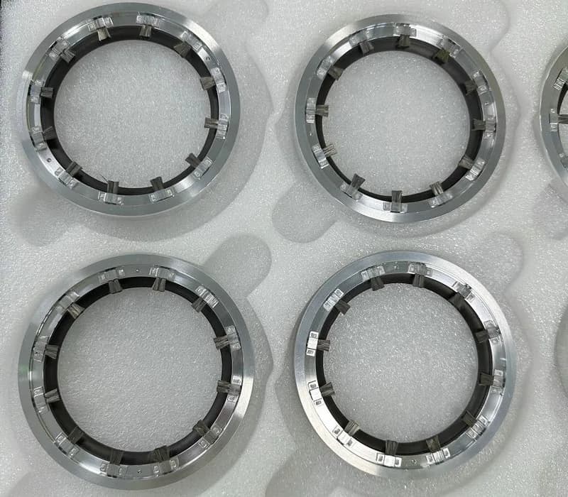
In one application-specific program, a customer needed a shaft grounding ring that also incorporated a sealing or contamination-control feature for a dusty operating environment. The request was not treated as a simple add-on: the sealing geometry had to be reviewed so it would not interfere with conductive fiber contact, and the combined structure had to match the available installation space. The path followed a design review, prototype samples, and installation evaluation before any production decision. That type of feature is an application-specific requirement—it should not be assumed transferable to unrelated motors or environments without a new review.
OEM Projects Requiring Validation and Scalable Production
OEM programs often need more than a one-off special dimension. When a custom shaft grounding ring is under consideration, a controlled sequence is usually more useful than an informal sample request:
- Drawing review
- Preliminary design
- Prototype
- Application validation
- Design adjustment
- Production review
When standard structures cannot meet the envelope or program needs, review a: custom shaft grounding ring
Repeatability, drawing control, installation consistency, sample validation, and production scalability should be part of the discussion. A prototype that fits one motor is not the same as a design ready for volume supply. Custom work is justified when standard structures cannot meet geometry, environment, or program requirements—not because custom is assumed to be a better default.
Standard vs. Custom Shaft Grounding Ring Review
| Factor | Standard Solution May Fit | Custom Review May Be Needed |
|---|---|---|
| Shaft geometry | Nominal diameter and contact zone fall within standard assumptions | Non-standard diameter, tolerance, runout, contact width, or contact position |
| Installation space | Radial and axial clearance support a solid or arc-shaped standard mount | Envelope too tight, retrofit access limited, or bracket/integration required |
| Rotational speed | Speed and duty align with the intended design window after review | High or unusual speed profiles that may affect contact stability and validation |
| Operating environment | Dry industrial conditions consistent with the selected structure | Oil mist, oil cooling, heavy contamination, or other duty that should be re-evaluated |
| Mounting interface | End shield / housing accepts the standard fastening layout | Non-standard housing, seals, shoulders, or restricted fastening positions |
| OEM validation / production program | Standard part with normal sample confirmation | Drawing-controlled design, prototype validation, and scalable production review |
In every row, the outcome depends on the application. A factor listed under “custom review” does not automatically require a new design; it means the case should be reviewed before a standard assumption is locked.
What to Send VOLSUN for an Engineering Review
Providing these inputs helps determine whether an existing standard configuration is suitable before a custom design is considered:
- Motor type and application
- Shaft diameter and tolerance
- Maximum rotational speed
- Installation drawing
- Installation photos
- Available radial space
- Available axial space
- Operating temperature
- Dry / oil-mist / oil-cooled environment
- Prototype quantity
- Estimated annual quantity
Incomplete inputs do not stop a preliminary discussion, but they do increase uncertainty. Clear geometry, space, speed, and environment data usually decide faster whether a standard ring may be suitable or whether a custom design path should be opened.
Conclusion
Standard shaft grounding rings remain a practical first path for many motors when geometry, space, speed, environment, and mounting fall inside the intended design window. Custom design should be considered when those conditions fall outside that window—or when an OEM program needs drawing control, validation, and scalable production—not because customization is automatically better.
Start with the application facts. Review whether a standard solid or arc-shaped ring may fit. Move to custom design only when the review shows it is needed.
Need a Shaft Grounding Ring for a Non-Standard Motor Design?
Send us your motor drawing, shaft dimensions, maximum speed, installation space, operating environment, and project requirements. Our engineering team can review whether a standard or customized shaft grounding solution is more suitable.
Submit Your Motor Requirements