Shaft Grounding Ring vs. dV/dt Filter and Common-Mode Reactor: Which Protects VFD Motor Bearings?
|
Compare a shaft grounding ring with a dV/dt filter and common-mode reactor for VFD motor bearing protection. Learn what each reduces and when a motor may need more than one.
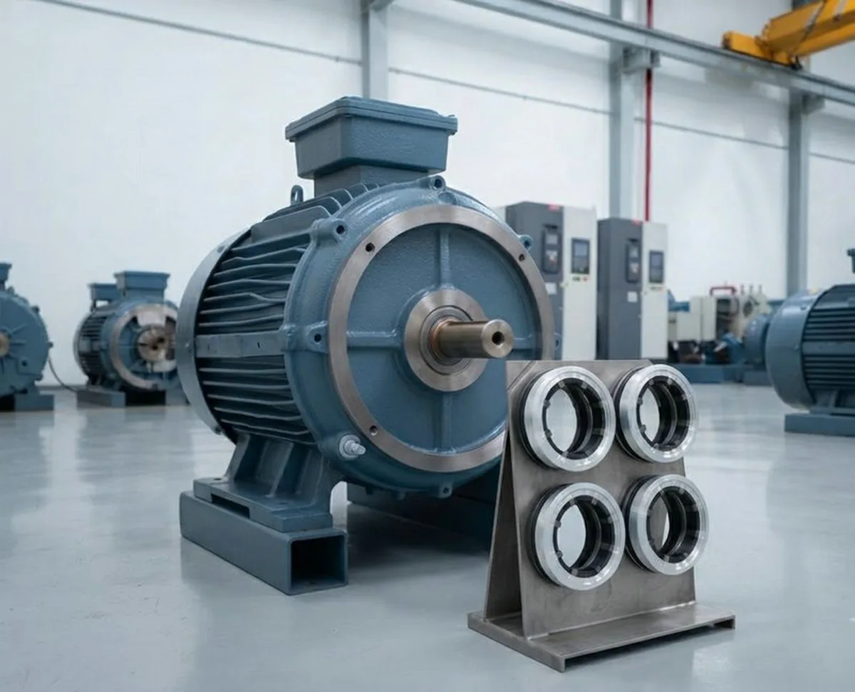
Variable frequency drives improve efficiency and speed control, but their high-frequency PWM switching can produce shaft voltage and bearing current that damage motor bearings over time. Several mitigation options are commonly discussed: shaft grounding rings, dV/dt output filters, and common-mode reactors. (Insulated bearings are a related but separate option, covered in a dedicated comparison.) These solutions are often treated as interchangeable, but they address different parts of the same problem. Choosing the wrong one—or using only one when a combined approach is needed—can leave a motor vulnerable.
This article explains how each solution works, what it actually reduces, and when a VFD motor may require more than one. It is a comparison of protection mechanisms, not a buying guide; for product selection and mounting practice, use the linked guides.
Quick Answer
A shaft grounding ring provides a controlled, low-impedance path that diverts shaft current to the grounded motor frame, reducing the voltage that remains on the shaft. A dV/dt filter sits at the VFD output and reduces the voltage rise rate and overshoot of the PWM waveform, which lowers the capacitive coupling that drives shaft voltage. A common-mode reactor is a series inductor on all phases that reduces common-mode current flowing in the motor cable and therefore the common-mode voltage at the motor terminals. None of these is universally sufficient alone: the ring acts on the shaft after voltage has built up; filters and reactors reduce the source magnitude but do not directly discharge the shaft. Many installations combine a ring with source-side filtering.
Why VFDs Stress Motor Bearings
PWM switching in a VFD creates common-mode voltage on the motor windings. The steep voltage edges of each switching transition—expressed as high dv/dt—drive larger instantaneous capacitive current through every parasitic capacitance in the motor system. Through capacitive coupling between the stator and rotor, this voltage can appear on the rotating shaft. When the shaft-to-frame voltage exceeds the breakdown threshold of the bearing lubricant film, current discharges through the bearing. Repeated discharges cause electrical discharge machining (EDM) damage: pitting on the bearing raceway, a frosted surface finish, and eventually bearing fluting and premature failure.
Two distinctions matter for choosing protection. Shaft voltage is not the same as bearing current: shaft voltage is the electrical stress on the rotating shaft relative to a reference, while bearing current is what actually flows through a bearing path. And there is no single safe shaft-voltage threshold that applies to every motor and drive; the right judgment depends on VFD topology, switching frequency, frame size, cable length, grounding arrangement, bearing configuration, insulation, coupling, speed, lubrication, the actual waveform, and the bearing-current mechanism.
For the mechanism in detail: What Causes Shaft Voltage in VFD Motors?
For a symptom-first diagnosis: What Causes VFD Bearing Failure?
How a Shaft Grounding Ring Works
A shaft grounding ring uses conductive microfibers that make continuous contact with the rotating shaft and connect to the grounded motor frame. When shaft voltage builds up, the ring provides a controlled, low-impedance path for that charge to flow to ground before it can discharge through the bearing lubricant film.
The key characteristic is that the ring is active with the shaft: it reduces the voltage that remains on the shaft during operation. It does not block current; it redirects it. For this to work, the ring must be correctly positioned on a clean shaft surface, properly secured to the motor housing or end shield, and connected to a reliable ground path.
VOLSUN's solid shaft grounding ring (VS-RD/RDW) and arc-shaped shaft grounding ring (VS-ST/STW) both use metallized carbon-fiber contact. They differ in installation approach: the solid ring is installed as a complete ring, while the arc-shaped version can be fitted without removing the shaft coupling—useful for retrofit work.
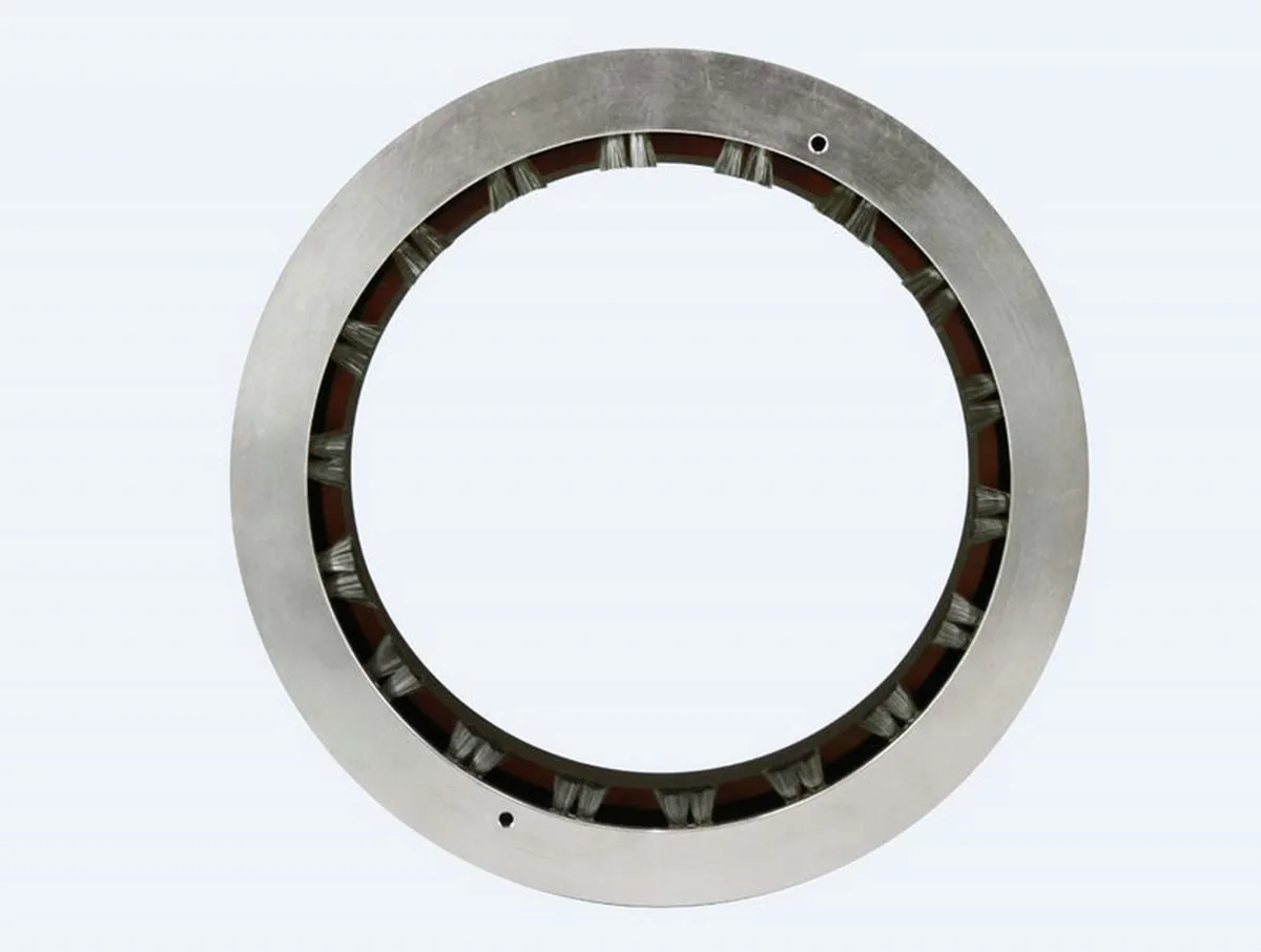
Solid ring product family: VS-RD / VS-RDW solid shaft grounding ring
Arc-shaped ring for retrofit or constrained installations: VS-ST / VS-STW arc-shaped shaft grounding ring
Why the ring is used at all: Why VFD Motors Need Shaft Grounding Rings
How a dV/dt Filter Works
A dV/dt filter is installed at the VFD output, between the drive and the motor cable. It reduces the rate of voltage change (dv/dt) and the overshoot or reflection of the PWM pulses. By slowing the steepness of the waveform, it reduces the capacitive current that couples into the motor and therefore lowers the shaft-voltage drive.
The filter does not connect to the shaft; it acts on the source waveform. Its effectiveness depends on the switching frequency, cable length, motor size, and drive design. It reduces the magnitude of the shaft-voltage drive but does not guarantee elimination of shaft voltage, and it does not provide a shaft-to-ground discharge path.
A dV/dt filter is most often considered where long motor cables cause reflected waves and high dv/dt, or where waveform control at the motor terminals is a design goal. It is a cable- and drive-side measure, complementary to a shaft-side measure such as a grounding ring.
How a Common-Mode Reactor Works
A common-mode reactor is a series inductor inserted in all three phases at the VFD output. It opposes common-mode current flowing in the motor cable and reduces the common-mode voltage present at the motor terminals. Because the shaft voltage is driven by that terminal common-mode voltage through the motor's internal capacitances, lowering it reduces the voltage available to couple onto the shaft.
Like the dV/dt filter, a common-mode reactor is a source-side measure. It reduces the magnitude of the common-mode drive but does not provide a shaft-to-ground discharge path, so residual shaft voltage can remain. A reactor and a dV/dt filter are related but distinct: the reactor limits common-mode current, while the dV/dt filter shapes the voltage edges. They are often combined in output-filtering packages.
Shaft Grounding Ring vs. dV/dt Filter vs. Common-Mode Reactor
| Factor | Shaft Grounding Ring | dV/dt Filter | Common-Mode Reactor |
|---|---|---|---|
| Working principle | Provides a controlled low-impedance path from shaft to grounded frame | Reduces dv/dt and overshoot of the PWM waveform at the VFD output | Series inductance limits common-mode current in the motor cable |
| What it reduces | Shaft voltage, by diverting charge to ground | Capacitive coupling, by slowing voltage edges | Common-mode current and terminal common-mode voltage |
| Where placed | On the motor shaft (drive end or non-drive end) | At the VFD output, before the motor cable | At the VFD output, in series with the phases |
| Acts on | The shaft-to-frame path after voltage builds up | The PWM source waveform | The cable common-mode current |
| Shaft-voltage discharge | Actively reduces it by diverting to ground | Reduces the drive; does not discharge the shaft | Reduces the drive; does not discharge the shaft |
| Retrofit effort | Ring mounts without bearing change; split ring needs no full teardown | Filter added at the drive cabinet | Reactor added at the drive cabinet |
| Main limitation | Does not block current on its own; depends on install quality and ground path | Source-side only; does not eliminate shaft voltage alone | Source-side only; does not eliminate shaft voltage alone |
| Typical use | Smaller and medium motors with shaft-to-ground discharge | Long cable runs, high dv/dt, waveform control | Common-mode current reduction, terminal-voltage control |
When a Shaft Grounding Ring Is the Primary Measure
A shaft grounding ring is often the first measure considered for smaller and medium-sized VFD motors where shaft-to-ground capacitive discharge current is the primary concern. Because it diverts shaft voltage proactively, it reduces the electrical stress that reaches both bearings simultaneously.
- The motor is driven by a VFD and shows elevated shaft voltage
- Bearing failure has been diagnosed as EDM-related, with pitting or a frosted raceway
- Retrofit is required without bearing replacement
- The motor is smaller and shaft-to-ground discharge current is more likely than circulating current
- Installation space allows mounting a solid or arc-shaped ring on the drive or non-drive end
Installation guidance: How to Install a Shaft Grounding Ring
When a dV/dt Filter or Common-Mode Reactor Is Warranted
Source-side filtering is worth considering when long motor cables cause reflected-wave high dv/dt, or when common-mode current and terminal voltage must be reduced at the source. These are drive- and cable-side controls that complement, rather than replace, a shaft-side measure.
- Long motor cable runs where reflected waves raise dv/dt at the motor
- High VFD switching or carrier frequency
- Multiple motors fed from one drive output
- Motor terminals measured with high common-mode voltage
- A design goal of controlling the PWM waveform before it reaches the motor
When a VFD Motor May Need Both
For larger VFD motors, high carrier frequency, long cables, or where circulating bearing current is also present, a ring on the shaft plus source-side filtering addresses both the shaft discharge and the source magnitude. Neither alone may be enough; a coordinated approach is often specified by OEM or motor manufacturer guidelines.
An important note: filtering that only reduces the source magnitude may still leave residual shaft voltage, so a grounding ring remains useful to provide the discharge path. Conversely, a ring alone does not reduce the source waveform. The two are complementary, not redundant.
Motor Protection Selection Checklist
Providing the following information makes it possible to review which protection strategy—grounding ring, dV/dt filter, common-mode reactor, or a combination—may be appropriate for a specific motor and application:
- Motor power rating and supply voltage
- VFD make and model
- VFD switching or carrier frequency
- Motor cable length between drive and motor
- Shaft diameter and available mounting space (drive end and non-drive end)
- Rated speed and maximum operating speed
- Drive-end and non-drive-end bearing types and designations
- Whether an insulated bearing is already installed (and on which end)
- Connected equipment and shaft coupling type
- Operating environment (dry, oil mist, oil cooled, dusty, washdown)
- New design or retrofit situation
- Measured shaft-voltage waveform or peak value, if available
For the full selection input framework: How to Select a Shaft Grounding Ring for EC and VFD Motors
Frequently Asked Questions
Can a dV/dt filter replace a shaft grounding ring?
Not always. A filter reduces the source magnitude but does not provide a shaft-to-ground discharge path. If residual shaft voltage still exceeds the bearing threshold, a grounding ring may still be needed. They address different parts of the problem and are often complementary rather than interchangeable.
Does a common-mode reactor eliminate shaft voltage?
It reduces the common-mode drive at the motor terminals, which lowers shaft voltage, but it does not eliminate it and does not discharge the shaft. A ring may still be required depending on the residual level and the bearing arrangement.
Should the filter or reactor be installed at the VFD or at the motor?
These are typically installed at the VFD output, between the drive and the motor cable, because they act on the PWM waveform and cable common-mode current. A shaft grounding ring is mounted on the motor shaft. They operate at different points in the system, which is why they are often used together.
What shaft-voltage level means a ring or filter is needed?
There is no single threshold that applies to all motors and drives. Shaft-voltage measurement, interpreted alongside motor size, VFD switching frequency, cable length, grounding arrangement, and observed bearing condition, gives a more complete picture. A single peak reading is not sufficient to choose a strategy without the application context.
Conclusion
A shaft grounding ring, a dV/dt filter, and a common-mode reactor each protect VFD motor bearings from a different angle. The ring diverts shaft current to ground; filters and reactors reduce the source magnitude. They are not interchangeable, and many installations use more than one. The right combination depends on motor size, VFD characteristics, cable system, bearing configuration, and operating environment.
Review the inputs in the checklist above before specifying a protection strategy. For a different comparison perspective, see the shaft grounding ring versus insulated bearing article, and for product options explore the VOLSUN shaft grounding ring families.
Another comparison angle: Shaft Grounding Ring vs. Insulated Bearing
Explore grounding ring options: VOLSUN shaft grounding ring products
Need sizing help?
Send motor nameplate data and shaft diameter - we respond within 24 hours.
Contact & RFQ